Most of the definitions are taken from the Glossary Chapter by Alexander T. Wells, " Airport Planning and Mangement", 3 rd Edition, McGraw-Hill, 1996
A. Classification:
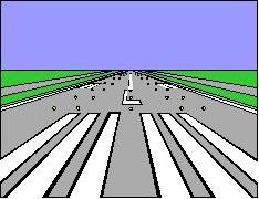
(i) Visual Runway – VFR operations only, runway does not include any straight in instrument procedure and no instrument designation on a FAA approved layout plan.
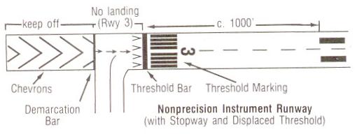
(ii) Nonprecision Instrument Runway has an instrument approach procedure using air navigation procedures with only horizontal guidance for which straight-in non precision instrument approach procedure has been approved
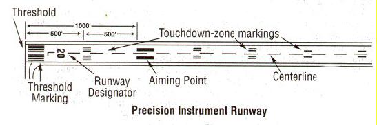
(iii) Precision Instrument Runway has an ILS system or Precision Approach Radar (PAR), Differential GPS, Microwave Landing Systems, and Transponder Landing Systems
B. Runway Orientation:
Runway Orientation is the magnetic bearing or compass heading of the centerline of the runway. Landings and take off best done into wind. Runways are oriented in direction of prevailing wind (95% usability factor). Historical meteorological data used to determine prevailing winds. Sometimes a "crosswind" runway is also required to meet the 95% usability factor.
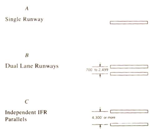
Runway Configuration is the layout or design of a runway or runways, where operations on the particular runway or runways being used at a given time are mutually dependent. A large airport can have two or more runway configurations operating simultaneously.
1. Single – an airport having one runway
2. Parallel- two or more runways at an airport whose centerlines are parallel
Close parallel( centerlines are less than 2,500 feet apart )
Intermediate parallel ( centerlines are 2,500 –4,300 feet apart )
Far parallel ( centerlines are more than 4,300 feet apart )
3. Open V-are two intersecting runways whose extended centerlines intersection beyond their respective thresholds 4. Intersecting- two ore more runways that cross or meet within their lengths
Diagrams of Runway Configuration
Reference: 2, page 206-207
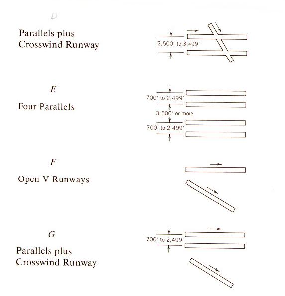
A. Basic markings- markings used for VFR operations include centerline, and runways designation numbers (runway orientation) and if required letters indicating left or right. B. Instrument Marking-markings on runways served by nonvisual navigation aids and intended for landings under IMC conditions, consist of basic markings plus threshold marking C. All weather Markings- markings on runways served by non visual precision approach aids and on runways having special operational requirements, consisting of instrument markings plus landing zone marking and side strips.
Visual Runway Markings
Reference: 4
Precision Instrument Runway Markings
Reference: 4
Non Precision Instrument Runway
Reference: 4
Runway lights are those lights with a prescribed angle of emission used to define the lateral limits of a runway. Runway light intensity may be controllable or preset. Lights are uniformly spaced at intervals of approximately 200 feet.
A. Approach lights
Sequence- are sequence flashers, that include lines of white strobe lights, that illuminate in sequence to guide the pilot's eyes towards the runway centerline. threshold lights – is lighting arranged symmetrically about the extended centerline of the runway identifying the runway threshold. They emit a fixed green light.
B. Glide Slope Indicators
VASI -Visual Approach Slope Indicators, An airport lighting facility in the terminal area navigation system used primarily under VFR conditions. It provides vertical visual guidance to aircraft during approach and landing by radiating a directional pattern of high intensity read and white focused light beams which indicate to the pilot that he or she is "on path" if the pilot sees red/white, " above path" is white/white, and "below path" if red/red.
PAPI - Precision Approach Path Indicators is another visual approach path indicator and gives more precise indications to the pilot of the approach path of the aircraft and used only one bar. The PAPI consists of four lights on either side of the runway. The PAPI gives five approach angles and has a transition from one color to another.
| Color | Angle |
| WWWW | High > 3.5 deg |
| WWWR | Slightly High 3.5 deg |
| WWRR | On slope 3 deg |
| WRRR | Slightly Low 2.7 deg |
| RRRR | Low < 2.3 deg |
C. Other Runway Lights
White touchdown zone lights – give depth to the pilot's perspective view of the runway, and mark 2,500 f eet long touch down zone Centerline Zone Runway Edge lights (white) are mounted not more than 200 ft apart and are white except at the last 2,000 feet of an instrument runway in the direction of aircraft operations.
Runway edge lights are typically visible through 360o
Snow lights- stand well above the average level of snowfall marking the runway edges when other runway lights are buried beneath it.

Reference: 3, Page 108
A. Taxiways- A defined path, usually paved, over which aircraft can taxi from one part of an airport to another. Taxiways are marked by green center lights and blue edge lights. Taxiways lead to runway entrances and exits. Most general aviation airports have right angle exits, however many commercial airports have turnoff taxiways or high speed exits that permit landing aircraft to exit the active runway without coming to a complete stop on the runway. Most taxiways are the shortest distance between terminal and runway
B. Holding Areas or Run up Areas Runup areas are used by propeller and turboprop aircraft for engine checks prior to takeoff. These are almost always located near ends of runways. Holding bays allows for aircraft to bypass one another if there is a change in departure sequencing.
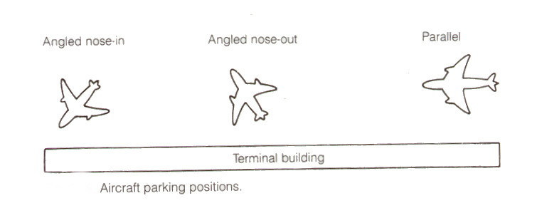
C.Ground Control Ground traffic control at large airports takes responsibility to moving aircraft from terminals to taxiways. Lineman guide aircraft to final parking area at terminals.
D. Aircraft Parking Aircraft parking is usually: nose in, nose out, or parallel .
Reference: 3 page 116
Most of the definitions are taken from the Glossary Chapter by Alexander T. Wells, " Airport Planning and Mangement", 3 rd Edition, McGraw-Hill, 1996