David G. Ullman, Dept. of M.E., Oregon State University.
Thomas G. Dietterich, Dept. of C.S., Oregon State University.
Larry A. Stauffer, Dept. of M.E., University of Idaho.
ABSTRACT
This paper describes the task/episode accumulation model (TEA model) of non-routine
mechanical design, which was developed after detailed analysis of the audio and video protocols
of five mechanical designers. The model is able to explain the behavior of designers at a much
finer level of detail than previous models. The key features of the model are (a) the design is constructed by incrementally refining and patching an initial conceptual design, (b) design
alternatives are not considered outside the boundaries of design episodes (which are short
stretches of problem solving aimed at specific goals), (c) the design process is controlled locally,
primarily at the level of individual episodes. Among the implications of the model are the
following: (a) CAD tools should be extended to represent the state of the design at more abstract
levels, (b) CAD tools should help the designer manage constraints, and (c) CAD tools should be
designed to give cognitive support to the designer.
1. Introduction
This paper presents a model of the mechanical design process. The purpose of a design model is
explanation and prediction. A design model should explain how the design process unfolds--why
it succeeds in some cases and why it fails in others. A model should also be able to predict future
successes and failures and provide some estimate of the resources needed to develop good
designs.
The model described in this paper, which we call the TEA model (task-episode accumulation
model), is still under development, and it does not provide as much predictive power as we
would like. It does, however, explain many aspects of the design process, and it provides
significant insight into the way mechanical designs are developed.
The major reason for developing design models is to improve the design process--to raise the
quality of the designed products and improve the efficiency of the designers. There are three
major avenues to pursue: development of design aids, improvement of design education, and
complete automation of some design tasks.
Developers of design aids need to know what proportion of the design process they are currently
assisting. They can benefit by identifying new aspects of design where assistance could be provided.
Design educators are interested in understanding what kinds of knowledge designers need. Is
there knowledge about design, independent of a specific technology, that can be taught? What
forms of expertise do successful designers have, and how can this expertise be transmitted to
students?
Researchers in artificial intelligence would like to understand how designers reason about the
evolving design. What constraints are brought to bear to guide the search for solutions? How
are potential solutions evaluated?
The research reported in this paper makes initial contributions in each of these areas. The paper
is organized as follows. Section 2 describes the research methods employed to gather and
analyze data on the design process. Section 3 gives an overview of the model. This is followed
by sections describing each of the major components: the design state (Section 4), the goal
structure (Section 5), the operators (Section 6), and the constraints (Section 7). There are some
short, example episode traces presented in Section 8. Sections 9 and 10 conclude with a
discussion of the implications of the model and the problems requiring further research.
The results presented in this paper are based on a two-year study of the mechanical design
process based on the evaluation of experienced mechanical designers solving real design
problems. Early results of this study along with details on the methods used have been previously
published (Stauffer, et al., 1987, Ullman and Dietterich, 1987, Ullman et al., 1987a, 1987b).
Other detailed results are reported in recent papers: details on the development of mechanical
design operators (Stauffer, 1987, Stauffer et al., 1987), details on the requirements of a state
representation for mechanical design (Tikerpuu and Ullman, 1988), and a comparison of high
level observations made in this study compared to those from other studies (Stauffer and Ullman,
1987).
2. Research Methods
Five mechanical design engineers of varying background and experience were given the initial
specifications for one of two fairly simple, yet realistic, industrial design problems. The
engineers were requested to think aloud as they solved the problems. Their verbal reports,
sketches, and gestures were video- and audio-taped for a period of 6-10 hours. The taped data
were then transcribed to obtain a "protocol" of the design session. This protocol was then
analyzed in a variety of ways to provide the data for this paper.
The two problems used in the study were the "battery contacts" problem and the "flipper-dipper"
problem. The battery contacts problem statement, in abbreviated form, is the following:
Design a plastic envelope (dimensions provided) and the electrical contacts to accept three
batteries to power the time clock in a new computer. The batteries (detailed dimensions
provided) must be connected in series and to an adjacent printed circuit board. The external
dimensions of the envelope are provided as are needed contact pressures. The volume is 50,000
units/month for three years and the assembly will use a robot.
Two subjects, S1 and S2, solved this problem.
The flipper dipper problem statement, in abbreviated form, is the following:
Design a mechanism that will accept a 10"x10"x.063" aluminum plate from a worker, lower one
side so that it just touches the surface of a chemical bath (to receive a chemical coating), lift the
plate off the bath surface, flip it over,lower and coat the other side, and present it to the worker
for removal. There were only to be 3 of these built.
Three subjects, S4, S5, and S6, solved this problem. More details on these problems can be found
in (Stauffer, 1987, Ullman et al., 1987a, 1987b).
Approximately 46 hours of data were taken. All of the data was transcribed and analyzed to
determine the general problem flow. Several detailed analysis techniques were tried on selected
parts of this data in an attempt to develop an analysis method that provided insight into the goal
structure of the design. It was found that an analysis based on tasks, episodes, and operators
(defined below) was most revealing and was reasonably repeatable by different researchers. Four
general types of tasks were identified: conceptual design, layout design, detailed design, and
catalog selection. For each protocol, all instances of each of these tasks were identified. Then
one instance of each was selected at random for detailed dissection. This yielded 19 sections
(one subject never performed a catalog selection task) constituting 204 minutes of data (8% of
the total data taken). The TEA model has been constructed from the detailed analysis of these 19
sections.
3. Overview of the Model
The TEA model is a problem-space model in which the fundamental components are the design
state and the design operators. The design state contains all information about the evolving
design including problem specifications, additional constraints introduced by the designer,
proposed designs, drawings, calculations, assembly plans, and so on. Design operators are
primitive information processes that modify the design state by performing calculations and
simulations, creating new proposed designs, evaluating proposed designs, and making decisions
to accept or reject proposed designs. The TEA model contains 10 operators: select, create,
simulate, calculate, compare, accept, reject, suspend, patch, and refine. These are discussed in
detail in Section 6.
The most important parts of the design state are the proposals and constraints. Proposals are
design elements created by operators as alternative ways of achieving some goal. For example,
to fasten two pieces of plastic together, the create operator might create three proposals:
adhesives, welds, and snaps. In mechanical design, proposals are normally forms, although they
can also be functions, plans, and constraints.
Constraints include specifications, requirements, needs, performance measures, and objectives as
these terms are used by other authors. A design problem normally begins with some rather abstract functional constraints. The designer may introduce other constraints based on past
experience (e.g., "don't use adhesives with plastics"). Additional constraints enter the design state
whenever a proposal is accepted. For example, once snaps are adopted for fastening the plastic
pieces, a new space constraint is derived: space must be reserved for the snaps. Hence, each
proposal can also be viewed as a constraint on the remainder of the design--once it is accepted
into the design. This observation is the rationale for including constraint propagation as an
important component in AI design systems (Steinberg, 1987) and is discussed in Section 7.
To accomplish a design, the design engineer applies the primitive operators in meaningful
sequences called episodes (Stauffer, 1987). An episode is a sequence of operator applications
that addresses some primitive goal. The nature and scope of primitive goals changes as the
design unfolds. Initially, a primitive goal might be "come up with a central concept for this
design" or "select a source of power for this machine". Later, a primitive goal might be "find
some way to mount the flipping frame to the arm". And still later, a primitive goal could be
"determine the tolerance on the shaft diameter." At any level, an episode requires and average of
56 seconds (maximum 80 seconds, minimum 32 seconds). The TEA model has six different
types of episodes: assimilate, document, plan, repair, specify, and verify. These are discussed in
Section 5.
An episode ends in one of three ways: (a) a solution has been accepted that satisfies the goal, (b)
no acceptable solutions has been found (all have been rejected) thus the goal itself has been
rejected (usually replaced by a reformulated goal), or (c) the goal is suspended to be reconsidered
at a later time. An episode may also be temporarily interrupted by a subepisode. The subepisode
addresses some goal whose solution is required by the original episode. After the subepisode is
completed, the episode is immediately resumed.
Within an episode, the decision about what operator to apply next is guided by a set of heuristic
rules. Many of these rules are presented in this paper, but a complete set of such rules has not
been developed. In future research, we plan to extend the set of rules and test them in a computer
simulation of the model.
When an episode is completed, the designer usually tackles another, closely related primitive
goal. A collection of related primitive goals is called a task. Generally, a task can be described
as a goal of larger scope, for example, "Layout the left battery contact" or "Dimension the
flipping frame". Within this larger goal, there will be several primitive goals: "determine the
length", "determine the width", "determine the shaft diameter", and so on. There are four major
types of tasks in the TEA model: conceptual design, layout design, detail design, and catalog
selection.
This completes the description of the basic components of TEA model. The model has four
important (and interrelated) features that should be noted. First, the TEA model addresses non-routine design tasks. None of the subjects in our study normally design the kinds of devices and
products required by our two problems. However, the subjects did all have some understanding
of the required technologies (e.g., simple electrical-mechanical devices, injection-molded
plastics, adhesives, etc.). Second, in the TEA model, the design is accumulated gradually by the
incremental contributions of each operator, hence the name "task/episode ACCUMULATION
model". Non-routine design, covered in this study, is not conducted by instantiating a prototype
or filling in some skeletal framework. Third, alternative designs are only considered WITHIN
episodes. By the time an episode is completed, one of the alternatives will have been selected
and accepted into the design state. Fourth, the design process is controlled locally, at the episode
and task level. The designer does not formulate and then execute a global design plan. Instead, a
central concept is developed and gradually extended to accomplish the design goals.
The terms used in the overview above are refined throughout the rest of this paper. In Table 1
this terminology is listed along with references given to the sections of the paper where each term
is discussed.
1. Levels of Abstraction (see Section 4.2)
A. Level 1, Abstract
B. Level 2, Intermediate
C. Level 3, Concrete
2. Constraints (see Section 4.3)
A. Given
B. Introduced
C. Derived
3. Goal Structure (see Section 5.)
A. Tasks
1. Conceptual Design
2. Layout Design
3. Detail Design
4. Catalog Selection
B. Episodes
1. Assimilate
2. Plan
3. Specify
4. Repair
5. Verify
6. Document
4. Operators (see Section 6.)
A. Generate
1. Select
a. State Select
b. Memory Select
2. Create
B. Evaluate
1. Calculate
2. Simulate
3. Compare
C. Decide
1. Accept
2. Reject
3. Suspend
4. Patch
5. Refine
Table 1 Mechanical Design Model Terminology
Now that the general components of the model have been reviewed, the sections that follow
describe each of these in more detail.
4. The Design State
As mentioned above, the design state is the sum of all information about the design that has been
processed by the designer. In particular, the state includes the functional and geometric constraints on the design, descriptions of the geometry, configuration, and materials for all forms
involved in the design, functionality of the design, manufacturing information, and so on. All of
this information must be represented in some way and stored in some location.
4.1 Where the design state is stored
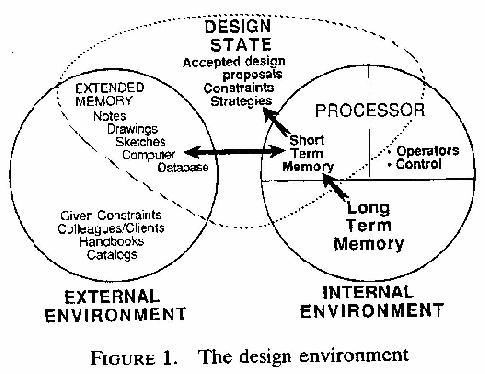
Figure 1 depicts the environment in which the design takes place. It is based on the models of
information processing psychology developed by Newell and Simon (1972) (Stauffer, 1987).
The figure can be viewed as a "map" of the locations in which information may be stored. It is
divided into internal locations (i.e., inside the mind of the designer) and external locations (i.e.,
outside the mind of the designer). Within the designer, there are two locations corresponding to
the two different kinds of memory: short-term memory (STM) and long-term memory (LTM).
There is also a "processor" that is responsible for applying operators and controlling the design
process. It is the goal of this study to identify the operators and the heuristics that control their
application. External to the designer there are many "design state storage locations" including
pieces of paper, CAD tools, handbooks, and colleagues.
The design state can only be represented in three locations: short-term memory, long-term
memory, and the so-called, external memory (which includes drawings and notes on pieces of
paper or stored in CAD tools). During the design process, other information is brought into the
design state from the environment through a process called assimilation. It is by assimilation that
such information as the problem specification, handbook information, or general knowledge
about design is brought into the design state. Information can be assimilated from various
external sources or from knowledge and experiences stored in long-term memory.
Each "location" has certain properties that affect how it can be used in design. Short-term
memory is very fast and powerful. Design operators can only operate on information that is
brought into short-term memory. Unfortunately, STM has limited capacity. Studies have shown
that it is limited to approximately seven "chunks" of information (Miller, 1956). (A chunk is a
meaningful unit of information the size of which varies with experience. Experts generally have
larger chunks than novices.
Long-term memory has essentially infinite capacity, but access is slow (from 2 to 10 seconds per
chunk). Access to long-term memory is also not direct. Instead, memories must be triggered by
some cue or retrieval strategy based on information in short-term memory. During design, parts
of the design state are stored in long-term memory and these are relatively easy to cue, because,
at any time, currently important parts of the design state are in short-term memory and can act as
pointers for the knowledge in the long-term memory.
Other information is also kept in long-term memory (e.g., knowledge about adhesives), but it
does not enter the design state unless it is specifically generated and assimilated.
All operations on the design and all information passing to or from long-term memory must pass
through short-term memory, so short-term memory forms a critical bottleneck for human
designers.
4.2 Levels of abstraction in mechanical design
The exact form in which the design state is represented in STM and LTM is the subject of
continuing research (Tikerpuu and Ullman, 1988). One critical property of this representation
that has been identified is its level of abstraction. (Sacerdoti, 1974, Adelson, 1985) A design
problem typically begins with a set of functional constraints expressed very abstractly. During
the design process, the level of abstraction of the design state is progressively reduced until it is
detailed enough to be manufactured.
The degree or level of abstraction of any element of the design state can be characterized by what
it explicitly describes and by what it omits. There is a continuum of degree of abstraction
ranging from the most abstract to the most concrete. For the purposes of describing the TEA
model, we have arbitrarily divided this continuum into three levels: Abstract, Intermediate, and
Concrete.
Each of these levels is defined below in operational terms. Separate definitions have been given
for the different kinds of "media" in which the state information may be represented:
verbal/texture, visual, and physical. Where necessary, distinctions have been made between form
representations and function representations.
Level 1. Abstract
Verbal/Textual
Both form and function represented in terms of qualitative descriptors (e.g. in the flipper-dipper problem statement, the machine must "lift the plate...,flip it over, lower and coat the other side")
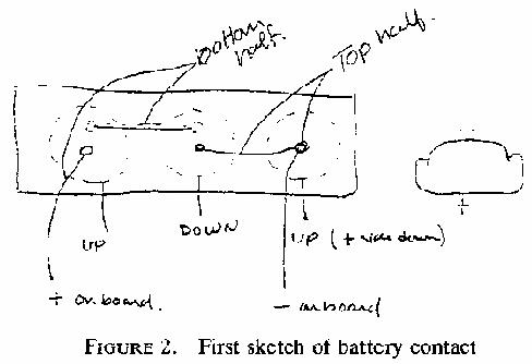
Visual
Forms represented as a rough sketch (back-of-the-envelope). These sketches may contain the
basic geometry and topology of the object. Major features and interfaces are contained in the
sketch. Functions are represented in block diagrams showing the flow of material, energy, and
signals as identified textually (defined above) or with symbols such as arrows (e.g. one subject
solving the battery contacts problem drew the first representation of a contact as in Figure 2).
Physical
There are no physical representations at this level of abstraction.
Level 2. Intermediate
Verbal/Textual
Both form and function are represented in terms of specific variable names or values for the overall measures of the design. This includes information on the manufacturing process and the material families for the forms (e.g. one subject solving the flipper-dipper problem defined an "arm" that had a "width" of "28 1/4 inches" early in the design ).
Visual
Forms represented as a sketch or drawing that is near scale or to scale. These sketches or
drawings may contain all the basic dimensions. All major features are complete (e.g. the "arm"
was represented at the time as in Figure 3).
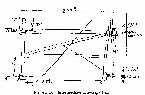
Functions represented in block diagrams have the variables identified textually (defined above). Results of analysis represented in graphs or plots.
Physical
Both form and function can be represented in crude models such as clay, paper, wood block, and
rough functional analogs (e.g. one subject solving the flipper-dipper problem made a paper
model of a part of his mechanism to confirm its operation).
Level 3. Concrete
Verbal/Textual
Both form and function represented in terms of specific variable names and values for all measures of the design and their tolerances. Bill of materials complete with specific materials and processes (e.g. many subjects made bills of materials and all wrote tolerances).
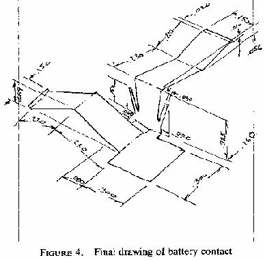
Visual
Forms represented as detailed drawings with tolerances. Functions represented in animations or
demonstrations of the actual hardware or prototypes of it (e.g. the "battery contact" contact was
finalized as in Figure 4).
Physical
Both form and function can be represented in final hardware or in static and working models of
the hardware. (Note: none of the designs were reduced to final hardware.)
These "levels of abstraction" will be incorporated into the heuristic rules in Section 5 of this
paper.
4.3 Constraints
Constraints play a central role in the TEA model. They can usually be viewed as limits on the
form or function of the device. Constraints are developed in one of three ways: (a) they are
GIVEN external to the solution of the design being considered, (b) they are INTRODUCED by
the designer based on his/her domain knowledge, or (c) they are DERIVED during the solution
of the design problem.
"Given" constraints appear in the initial statement of the problem, or they are imposed on the
design problem by the solution of other components not under the control of the designer responsible for the problem under consideration. The given constraints for the protocol experiments
were summarized above in Section 2.
"Introduced" constraints are those constraints imposed on the problem by the designer based
on specific domain knowledge. For example, subject S2 (working on the battery contacts
problem) early in his conceptual design imposed a constraint that he would not use adhesives,
because they are messy and hard to deal with. This is considered an "introduced" constraint,
because it was not imposed by the problem statement and it was not derived from decisions made
during the design process. Introduced constraints can be universal in nature. For example, our
subjects often verbalized a preference for "round" numbers over more precise quantities.
Introduced constraints can also be quite domain specific such as the adhesive knowledge above.
"Derived" constraints arise as a consequence of design decisions. In the battery contacts
problem, for example, the decision to place the contacts on the sides of the batteries resulted in a
derived constraint concerning the amount of space available for the contacts. This constraint is
derived from the constraint on the total available space and the previous design decision.
These constraint definitions complete the description of the design state. The next section
presents the goal structure of the design process.
5. The Goal Structure of Mechanical Design
According to the TEA model, the goal structure of the design process has three main levels. At
the highest level is the main goal comprising the satisfaction of the given constraints. This top-level goal is decomposed into finer goals, each of which is solved by a single task. These task-level goals are further decomposed into the primitive goals that are each addressed by an episode.
The remainder of this section describes the structure of task-level and episode-level goals and
design processes. Section 6 describes the individual operators that are used to satisfy the goals.
The top level goal is to design a machine which is subject to many stated restrictions on its
function and its form. These given constraints are usually dominated by some abstract functional
requirements on the operation of the device along with some less abstract, possibly very concrete
spatial and manufacturing demands. Additionally, these given constraints may be represented in
different ways: verbal, textual, visual, or physical. Lastly these given constraints may not all be
satisfiable; they may conflict with each other or with what is achievable. As an example, in one
of the problems solved by three of our subjects, a given constraint was that the machine needed
to "flip" an aluminum plate. In the TEA model this requirement is classified as a textually
represented, abstract, given constraint on the function. Another part of the description for the
same problem was a sketch (with dimensions) of the table top on which the device was to be
mounted. These dimensions (textual) and the drawing (visual) combined to describe spatial,
concrete, given form constraints.
Other constraints on this problem were left unstated, of course. Every design is constrained by
the laws of physics and by the desire to minimize costs and part count. The TEA model
considers these to be given constraints as well.
Below the top-level goal, there are three general kinds of task-level goals each addressed by a
task: conceptual design, layout design, and detail design. Detail on these tasks are given in
sections 5.1-5.4. In the protocol study, these tasks required from 8 to 20 minutes to be performed
with an average duration of 10.8 minutes. Each of these task-level goals focuses on the function
of the device, some assembly, some specific part, or a feature of a part. The task of catalog
selection (mentioned previously) usually addresses a subgoal that arises during a layout or detail
design task.
In the protocol data, contrary to many design models, the design process is not broken into
separate conceptual, layout, and detail design phases (there are conceptual, layout and detail
design tasks through out the design). Efforts were made to reduce the protocol data into separate
phases and develop a goal tree for the design. This was found not to be possible as the "phases"
are a management artifice and are not deriveable from the protocol data. For example, there were
several occasions in which problems identified during layout design of some component triggered the conceptual design of a new component or a new feature of an existing component.
Hence, tasks of different kinds are interleaved in the protocol analysis. It appears that the best
level to develop a goal tree is at the episode level as is demonstrated in Section 8.
Each task is composed of a sequence of episodes addressing primitive goals. Six types of
episodes that make up the tasks have been identified from the protocols. These are Assimilate,
Document, Plan, Repair, Specify, and Verify. They are defined as follows:
"Assimilate" episodes have the goal of bringing information from the external environment or the
long term memory into the design state. Usually the information being assimilated is constraint
information, but designers also bring into the design space specific design proposals or strategies
from their long-term memory, colleagues, and handbooks.
"Specify" episodes have the goal of clarifying or developing a design proposal into a more
specific description (lowering its level of abstraction). This is the workhorse of the episodes. If
the constraints were all known and the plan fully defined, the design process would reduce to a
sequence of specification episodes followed by the need to document the design.
"Planning" episodes have the goal of developing strategies for how to proceed. Planning
episodes do not help in solving the goal of designing a machine, but are a part of establishing the
goal structure necessary for the solution. In the protocol data, little planning was observed.
"Document" episodes have the goal of recording information textually or graphically in the
external environment with the purpose of communicating to others. In other words the goal of the
document episodes is not to specify any more information about the design but to record previous
results. However, it must be noted that often, even though the goal might be to document
information, new design decisions must be made because the designer discovers that the information to be documented is incomplete.
"Repair" episodes have the goal of altering previously specified information to repair a conflict
between a previously accepted design proposal and a constraint or a conflict between two or
more constraints. In other words, repair episodes take information accepted into the design state
and reconsider it in the light of conflicting constraints.
"Verify" episodes have the goal of repeating an episode to ensure that its results are still
acceptable. In the protocol data there were several instances of the designer going back and
reperforming the operations in an episode to verify decisions before the investment in them is too
great.
In the 204 minutes of data analyzed, the subjects performed 208 episodes. The distribution over
all the tasks is shown in Table 2. Note that this paper describes specify, document, assimilate
and plan episodes. Additional information on verify and repair episodes is in Stauffer (1987).
Assimilate Document Plan Repair Specify Verify
Conceptual 36% 0% 19% 3% 39% 3%
Layout 18% 6% 12% 8% 49% 6%
Detailed 3% 52% 8% 8% 23% 6%
Catalog Select 30% 11% 18% 0% 26% 16%
Total 19% 21% 13% 6% 34% 7%
Table 2: Episode Distribution
In analyzing the protocol data, it was much easier to identify episode boundaries than it was to
detect task boundaries. The reason for this is that the subjects did not solve the problems in a
particularly orderly fashion. A task focuses a series of episodes on a general "region" of the
design, but subjects often departed from this region to gather information or make decisions
regarding other, related, parts of the device. One good example of this behavior arose during the
layout task selected from S6's protocol. This task involved finding some method for mounting
the "flipping frame" (the frame that held the plate while it was flipped). This was a real sticking
point in the design. S6 would work on it for a while and then, when an acceptable solution was
not found, address another task, and return to the mounting problem later.
As a consequence of this interleaving and interruption of tasks, the flow of the design process is
best mapped by following the individual episodes. In the remainder of the paper, the tasks are
used only as a rough guide and the episodes are the primary focus.
The remainder of this section describes in detail the episode structure in each of the task types.
The heuristic rules given are numbered in brackets. These numbers are referred to in the example
episode traces in Section 8.
5.1 The Task of Conceptual design
Conceptual design is primarily concerned with assimilating the given constraints and specifying
forms to meet the functional given constraints. This specification is accomplished to at least an
abstract level.
In the reduction of the protocol data, 5 conceptual design tasks (totalling 68 minutes) were
selected at random--one from each subject's protocol. Within these tasks, the episodes are distributed as shown in Table 2. Clearly, the subjects are focused on assimilating information
(36%) and developing (specifying) design proposals (39%) in this stage of the design.
Some of the rules governing the sequence of episodes in conceptual design are as follows:
If the design state is empty (R1)
Then internalize the given constraints via assimilate episodes.
The first task begins with a series of assimilate episodes. Each episode has the subgoal of the
designer reading or otherwise considering (looking at samples or other hardware, talking to the
experimenter in the protocol recordings, talking to the client, etc.) a constraint and understanding
it. The design state is said to be empty at the start of the design process and these assimilation
episodes form the first conception of what the design is to become.
If assimilating given constraints (R2)
Then perform episodes with goals of breaking the given constraints into individual constraints
and considering each one at a time.
When the subjects were first given the problem description, they usually read through it twice.
The first time was a direct word-for-word reading, but the second contained many pauses to
evaluate constraints, relate the text to the figures, and assimilate other information not in the
problem statement. In general, constraints were assimilated in the order they appeared in the
problem statement. Some subjects compiled a written list of the major constraints. This list
frequently broke the given constraints into individual constraints, which were then assimilated
one by one. This process of individualizing the constraints must be based on the designer's
domain knowledge. Each constraint is evaluated before it is incorporated into the design state
(see Section 6.2 for more on evaluation).
Assimilation does not occur only during this early stage. Any time the designer brings
information from long-term memory or external sources into the design state, assimilation is
required (see Figure 1). Even the problem statement is reconsidered as the design unfolds. The
subjects frequently went back and reread the statement to assimilate details that had been skipped
during the initial task.
The following rule terminates this first period of assimilation:
If the given constraints have been assimilated to (R3)
the point that 1) the designer feels the problem is understood or 2) the constraints cannot be further understood without concepts to consider
Then develop design proposals.
In the protocols, the subjects each spent between 5 and 32 minutes understanding the constraints.
They then paused and often announced that they were ready to begin the design. This occurred in
spite of the fact that in many cases there were constraints that were obviously not well
understood or were wrongly interpreted. In most cases these constraint problems were resolved
later in the problem, but misinterpretations here in establishing the early state of the design were
often built on throughout the remainder of the design.
If a design proposal is to be developed (R4)
Then select the most important functional constraint or group of related constraints.
The primary goal of conceptual design is to specify forms to meet the given constraints. This is
accomplished by selecting a few of the constraints and generating a conceptual design to satisfy
them. This initial design is then elaborated to meet the remaining constraints. This is what is
meant by accumulation design in the acronym "TEA".
It is not clear when or how the subjects determine which constraints to pursue first. One
hypothesis is that each constraint is evaluated and ranked for "importance" as it is assimilated. A
reason for not believing this hypothesis is that separate "ranking" episodes were not observed in
the protocols. Another hypothesis is that subjects prefer to begin with functional rather than
form constraints, since functional constraints relate more directly to the purpose for which the
device is being designed. Most of the constraints initially focused on were functional constraints.
A third hypothesis is that constraints are considered "important" if they appear to be difficult to
satisfy. The less experienced subject in the battery contact problem (S1), for example, focused
on the constraint that the batteries must be connected in series. Subsequent episodes showed that
S1 was not sure exactly how to achieve a series connection, so for her, this constraint was
difficult. Subject S2, on the other hand, focused on a constraint that specified the contact
pressure on the batteries. When S2 made an initial drawing, he immediately drew a configuration for connecting the batteries in series. Hence, for him, the series connection constraint was
considered easy to satisfy. Clearly, the designer's prior experience is important in helping
him/her determine the degree of difficulty of each constraint.
If a functional constraint(s) has been selected (R5)
Then generate, evaluate, and accept a form design proposal for that constraint(s).
It is interesting to note that in domains where form and function can be aligned (e.g., so that a
functional decomposition corresponds directly to a form decomposition), this rule could be
applied repeatedly to carry out the entire design. While it is rare to find a domain where this
occurs, software and circuit design approach this ideal more closely than mechanical design.
Problems arise in all engineering fields when individual forms are engineered to do many
functions simultaneously (Sussman and Steele, 1980, Ulrich and Seering, 1988) and this can not
be avoided in most mechanical designs. Even static structures not only carry load but must
function as a stiffness, transfer thermal energy, etc. In the flipper-dipper problem, for example,
the same mechanism that allows the plate to be dipped may also assist in flipping the plate.
This has an important consequence for the design process: each design decision can potentially
affect every subsequent decision. The reason is that all subsequent design tasks must consider
the possibility that their goal can be achieved by modifying a previously specified form (i.e., to
save space) rather than by introducing some new form. Furthermore, even if the previously
specified forms are not modified, new forms must coexist with them. The constraints of space,
weight, and so on may make this impossible. In a functionally-decomposed design, by contrast,
each design decision on a given form only affects subsequent decisions concerning
subcomponents of that form.
As an example, consider subject S5. He began the flipper-dipper problem by focusing on the
functional constraint of dipping of the plate. His first form design proposal that was generated,
evaluated, and accepted was a ferris-wheel-type machine. This decision carried with it the
derived, functional constraint that the motion of the plate must be tangent to the water. This in
turn became a very important constraint on the development of the method to hold (another
function) and flip (yet another) the plate. This constraint became so imbedded in the design that
it was not later relaxable without paying the price of virtually starting all over again.
If forms have been accepted for the most important (R6)
functional constraints
Then the next goal is to develop forms for the next most important constraint(s).
After each decision to update the design state by accepting a design proposal, the constraints
(given, derived and introduced) still to be satisfied are reconsidered to find the most important
ones to use as the focus for the next goal. This is not to say the engineer keeps a long agenda of
constraints to satisfy but, when verbalized there were often three or four in perceived order of
importance. Of course this order changes as new, derived constraints developed. Additionally if
an episode was suspended due to a lack of information, the new, most important goal may be to
assimilate or in some other way specify the needed information to satisfy the suspended goal.
This behavior often gave rise to subepisodes (within episodes) to develop needed information.
Twenty-one percent of all episodes were subepisodes with the nesting sometimes three levels
deep.
5.2 The Task of Layout Design
Once the major forms have been conceptualized to satisfy the "important" (primarily functional)
constraints, the focus changes to specifying the components (assemblies and individual parts) at
decreasing levels of abstraction. There was generally a clear verbal demarcation at this point.
The subjects reported that they now understood what their solution would look like and that only
the "details" remained to be worked out.
In the reduction of the protocol data, five layout tasks (totalling 63 minutes) were selected at
random--one from each subject's protocol. Within these tasks, the episodes were distributed as
shown in Table 2. Notice that about half the effort is on specifying the design (49%).
Assimilation is much less common than it was during conceptual design (down from 36% to
18%), and documentation is still playing only a minor role.
Only one rule controls the selection of episodes during layout tasks:
If performing a layout design task (R7)
Then specify the design proposals to intermediate or concrete abstraction.
Layout is simply concerned with moving the design state to refined levels of abstraction. Most of
the interesting problem-solving behavior during layout design arises because of the need to repair
problems that arise during this process (see the discussion of evaluation and repair operators in
Section 6.2 and 6.3)
5.3 The Task of Detail Design
As the design becomes more finalized, the designer's attention gradually shifts to focus primarily
on documentation and continued refinement as needed. In the protocol analysis, detailed design
tasks were assumed to begin when the subject started making scale drawings rather than
sketches. However, long before this point the subject would usually have begun specifying
particular dimensions (and even tolerances) for some components. Unlike the clear demarcation
between the conceptual and layout tasks, where the subjects virtually announced they had a
concept defined, there was no observable transition between layout and detail design in the
protocol data.
Based on the definition of the levels of abstraction and with a desire to be consistent with
traditional terminology, the detail design task has been defined in the TEA model as focusing on
the complete refinement and the complete documentation of the design. This is captured by the
following rule:
If performing a detail design task (R8)
Then reduce all the form design proposals to concrete forms and document them.
As with the conceptual and layout tasks, 5 detail design tasks (totalling 61 minutes) were chosen
at random (one per subject). Within these tasks, the episode breakdown was as shown in Table
2. The breakdown shows the importance of documentation at this point (52%). In contrast to
earlier tasks, assimilation is virtually absent.
5.4 The Task of Catalog Selection
In addition to the three kinds of tasks discussed above, there was one other task that involved
significantly different kinds of problem solving: catalog selection design. The goal of a catalog
selection task is to select some part or assembly from a catalog. Four particular catalog selection
tasks were chosen for protocol analysis (one subject did not perform any catalog selection). The
episode breakdown was as shown in Table 2. This breakdown shows that during catalog
selection, the designer interacts with the catalog to assimilate new information as well as to
specify and document particular components. Catalogs play a significant role in suggesting new
design possibilities to the designer, as well as in providing the information the designer is
seeking.
The fact that catalog selection was different enough to constitute a new kind of task reveals two
important facts. First, it shows that the traditional sequential model of design involving three
phases (conceptual, layout, and detail) is incomplete. Second, it suggests that other kinds of
design tools (aside from catalogs) may also have a significant impact on the way designers
organize their design processes (e.g. intelligent CAD tools such as parametric design tools and
expert systems).
5.5 Planning Episodes
Although control of the design process is primarily carried out at the operator level, there were
occasions in which the subjects formed plans and verbalized them. These plans were usually
rather short-range, near-term plans. Their main purpose seems to be to evaluate whether a
proposed task is worth performing at the current time. One point of evidence in favor of this
hypothesis is that the plans, once formulated, were not followed very exactly.
Another hypothesis about planning is that plans are formed prior to tasks in which many
distractions are possible. For example, before picking up a catalog or handbook, subjects often
verbalized their plan for the catalog selection task. They would explicitly mention the strategy
they intended to use to locate the desired information. Such a plan may provide a kind of defense
against the possible distracting effects of the catalog or handbook. There is so much information
in such books that it is important to focus on finding the desired information in a fairly directed
way.
This completes the description of the task and episode types. The next section describes the
individual operators that make up these episodes and tasks.
6. The Mechanical Design Operators
The building blocks of the design process are the operators. Once selected by the controller
(under the guidance of heuristic rules), the operators are applied to change the state of the design.
To analyze the protocols, each utterance was considered separately (see Stauffer (1987) for
details of what constitutes an utterance). These utterances averaged 11 sec in duration each. The
average episode contained 5.4 utterances, and the average task 60 utterances. Generally, each
utterance reflects a change in the state of the design, so each is considered the result of the
application of an operator. In studying the protocol data, it was found that by defining 10 kinds of
operators, all episodes and tasks could be analyzed to a more detailed and more useful level.
The following sections define each of these 10 operators and present several heuristic rules for
applying the operators during design. The operators are broken into three groups: generation
operators, evaluation operators, and decision operators.
6.1 The Generation Operators
The generation operators bring design proposals, constraints, or strategies into consideration.
There are two such operators: Select and Create.
The "Select Operator" causes information to be brought into consideration in the short term
memory. The information is either old information obtained from the design state or new
information obtained from longer term memory or some external source.
The "Create Operator" introduces new information into short term memory, but the source of the
generated information is unknown. Many unverbalized steps may have occurred to generate the
information from long term memory.
During protocol analysis, the Select operator is used when it is possible to infer where the
information came from. Otherwise, the Create operator is used. These two operators are most
commonly used to introduce new constraints and new design proposals into the design state.
New constraints may be derived by combining previous design decisions with unverbalized
domain knowledge. They may also arise from mental simulations and visualizations, which are
also unlikely to be verbalized (Kant and Newell, 1982, Kant, 1985, Adelson and Soloway, 1984).
Similarly, new design concepts, especially during conceptual design, may arise from a memory
retrieval or via some visualization process. An important unsolved problem in design research is
to develop some technique for determining where these new ideas originate.
6.2 The Evaluation Operators
The evaluation operators serve to relate or compare information (especially a proposal and a set
of constraints) from the design state in order to make a decision. Three operators are used in
evaluation: simulate, calculate, and compare.
The "Simulate Operator" has the role of adjusting the representation of its arguments to the same
level of abstraction. This operation can range anywhere from "hand waving" to building paper
models, to performing formal mathematical simulations. Whatever the method, the purpose is the
same: to reduce the arguments to be used in a comparison to the same representation and level of
abstraction (Adelson and Soloway, 1984).
In order to compare two items, it is necessary to have them expressed at the same level of
abstraction and represented in the same language. For example, if there is a constraint that says a
part must fit in a 2.00+.005 inch slot and the abstract design proposal for the part just says that it
is "small", then it is impossible to compare the proposal to the constraint. The comparison can
be performed if either (a) the constraint dimension is translated into a verbal language (perhaps
"large" in this case), (b) the proposal dimension is given a precise numerical value (with
associated tolerance), or (c) both the constraint and the proposal are transformed to some
intermediate common level. The Simulate operator performs this transformation. In this
example, the constraint dimension of 2.00+.005 inches might be translated into a verbal
description by performing a mental simulation.
The "Calculate Operator" combines constraints or design proposals to derive new information.
The new information is in the same representation and at the same level of abstraction as the
initial information.
The calculate operator's purpose is to derive new information at the same level of abstraction.
Calculate operations employ logic, mathematics, and inference rather than search. Often
calculation is driven by the fact that there is a proposal for which no constraints directly apply for
comparison, but a calculation using existing constraints yields a constraint directly comparable to
the proposal. An example of this is where subject S5 is trying to evaluate a variable-speed (3.2
to 89 rpm) gear motor for use in his design. He knows that he must dip 40 plates per minute, that
his design will handle 3 plates per revolution, and that he can have a 3:1 chain drive reduction.
A quick mental calculation using the plate rate, plates per revolution, and the ratio gives a new
constraint (40/3*(1/3)= 3.33 rpm) which is directly comparable to the proposed motor. Note that
calculate usually is applied to develop new constraints whereas simulate transforms constraints
and/or proposals to a common level of abstraction prior to comparison.
The "Compare Operator" has three functions: (a) to relate a set of design proposals to a set of
constraints to determine whether the proposals satisfy the constraints, (b) to compare two
constraints to determine whether they are compatible, and (c) to compare two strategies to
determine which one is better.
In the 208 analyzed episodes, there were 141 compare and 75 calculate operators. In most cases,
each of these was preceded by a simulate operator so that evaluation usually appears as a simulate-compare or simulate-calculate pair. This makes sense, since information must be at the same
level of abstraction and in the same representation in order to apply the compare and calculate
operators.
The following rules are some of those identified in the protocol data used by the subjects to
control the application of these operators:
If the goal is to compare a design proposal(s) to a (R9)
constraint(s), and the proposal(s) and constraints(s) cannot be directly compared,
Then perform a simulate operation to put all the information in the same representation at the
same level of abstraction and then do the compare operation.
In about one third of the evaluation operations (75/216), the need was for new information rather
than a comparison of existing information:
If the currently selected information does not convey (R10)
the desired information
Then attempt to calculate new constraints from the existing ones in the same representation and
at the same level of abstraction otherwise select or create new information.
If a design proposal satisfies the constraints and if there (R11)
is another proposal(s) that was generated at the same time as the first one and at a similar level of abstraction
Then compare it to the constraints and against the previous proposal(s).
This last rule mentions the comparison of multiple proposals. Previous work (Ullman et al.,
1987a, 1987b) has observed that designers typically pursue only a single design proposal. One
hypothesis explaining this observation is that multiple proposals (especially detailed proposals)
are too complex to be handled well by human designers. The detailed analysis of the protocols
supports this hypothesis. Multiple proposals were compared in only 13% of the comparison
operations. Of these, the great majority were comparisons involving abstract proposals during
conceptual design. Only 25% of the multiple-proposal comparisons involved layout or detail
tasks.
To further limit the complexity of multiple-proposal comparisons, the designers usually (75% of
the time) focused the comparison on only a few constraints (e.g., comparing two proposals for
their cost, ease of assembly, etc.). When three proposals were to be compared, one was taken as
the focus, and the other two proposals were only compared to it rather than to each other.
Evaluation operators arise particularly often during catalog selection tasks. The designer
typically has a set of constraints in mind before picking up the catalog. The catalog can be
viewed as providing several alternative design proposals and constraints, all at the same level of
abstraction and in the same representation. As the designer assimilates each of these catalog
proposals and constraints, he must compare each of them to his design constraints.
If searching a catalog or handbook (R12)
Then every new proposal examined in the catalog must be compared to the existing constraints.
Another place where Compare operators are frequently applied is during the assimilation of
constraint information from outside sources.
If assimilating a constraint (R13)
Then use the compare operator to evaluate it relative to existing constraints, analogous designs
from memory, and other existing design information.
Even during the reading of the initial problem specification, each constraint is evaluated by the
designer to see if it "makes sense". This includes comparing it to previously assimilated
constraints to determine which constraints conflict and comparing it to analogous designs from
memory in order to understand what the constraint means and how it might be achieved. An
important example concerned subject S5 (flipper-dipper problem). As he was assimilating the
constraint concerning the way the plate must touch the chemical bath, he compared it to the
motion of a microtome (a device for cutting thin samples for microscopic analysis). This helped
him understand the constraint. Unfortunately, the analogy led him to focus incorrectly on the
idea that the plate must move tangent to the surface of the bath, and this greatly complicated his
design.
6.3 The Decision Operators
Once an evaluation is made, the decision operators can be invoked. There are five decision
operators: Accept, Reject, Suspend, Patch, and Refine.
The "Accept Operator" is used if the comparison results are satisfactory. Then the design
proposal, constraint, or strategy under consideration is accepted as a part of the design state. An
acceptance is not permanent, however, as there are repeated cases of an accepted decision later
being reconsidered and rejected.
The "Reject Operator" is invoked if the comparison results are not satisfactory. As above, a rejection may not be permanent, as subsequent recomparison are possible (e.g., with new constraints or with a redefinition of what constitutes satisfaction).
It is not evident from the protocol data what constitutes satisfaction. One hypothesis is that
designers are able to make an estimate, based on the given constraints, of how good a solution is
attainable for the problem. Proposals that approach this estimate are considered satisfactory,
while proposals that fall short are not. According to this hypothesis, the designer may need to
revise this estimate in the light of repeated failure to find a satisfactory solution.
Not all evaluations result in an accept or reject decision. Two other things can occur. First, the
evaluation can be suspended while additional information is gathered. Second, the results of the
evaluation can be used to guide further development of the proposal, and then another evaluation
can be made.
In the first case, the Suspend operator is applied:
The "Suspend Operator" discontinues work on the current episode and establishes a new goal to
generate and evaluate the information needed to complete the suspended episode.
Twenty-five percent of all episodes are suspended to gather more information or work on some
other aspect of the design.
In the second case, either the Refine or the Patch operator is applied:
The "Refine Operator" continues to develop the design proposals, constraints, and strategies in
the episode to a more refined state, guided by the result of the preceding evaluation.
The "Patch Operator" keeps the design proposal, constraint, or strategy at the same level of
abstraction but alters it in some way guided by the result of the preceding evaluation.
The distinction between Refine and Patch is that information patched remains at the same level
of abstraction and only changes some aspect of the design proposal. Refine does not change the
proposal, but elaborates it, to more detailed levels of abstraction.
There is some question about whether Refine and Patch should be considered decision operators
or generation operators. Clearly they are both. We have placed them here because they are
invoked as the direct result of an evaluation, like other decision operators. But they can be
viewed as closing the loop between decision-making and generation of additional information.
Some of the heuristics that control the application of the decision operators are:
If the design proposal compares satisfactorily with the (R14)
constraints
Then accept it.
With one episode per minute or an estimated 600 episodes per 10 hour protocol and with an
average of .91 acceptances per episode there were 550 decisions to accept information into the
design state. In other words, there are approximately 550 changes in the design state that led from
the given constraints to the completed design in the protocol data.
If a design proposal, constraint, or strategy is common (R15)
knowledge or is very abstract
Then accept without evaluation.
In 33% of the uses of the Accept operator, information is accepted into the design state without
any observable evaluation. There are three hypotheses that explain this observation: (a) an
evaluation occurred but it was not verbalized, (b) the information being considered was so
familiar to the designer that no evaluation was needed, or (c) the information being considered
was so abstract that little was risked by accepting it. The third hypothesis is particularly
applicable early in the design process.
Another case where there is no evaluation before an Accept operator arises with patches and
refinements:
If a patch or refinement (performed in response to a (R16)
comparison) is guaranteed to satisfy the relevant constraints
Then accomplish the patch or refinement and accept without re-executing the comparison.
In 74% of the patches and refinements, the designer was evidentially confident that the change
made was guaranteed to satisfy the constraint(s) in the comparison, so no re-comparison was
needed. In the remaining 26% of the cases where the comparison was repeated, it appears that
another constraint was brought into the evaluation of the improved proposal. These observations
support the hypothesis that designers have a form of "patching" expertise. This expertise relates
different failures or constraint violations to appropriate patches or refinements.
Of course proposals are sometimes rejected. This was relatively rare: only 12% of the 257
proposals considered were rejected. The rules governing rejection (versus patching) are
If a proposal is unsatisfactory (when compared to the (R17)
relevant constraints) and little has been invested in it
Then reject it or (if a simple fix is evident) patch it.
If a proposal is unsatisfactory (when compared to the (R18)
relevant constraints) and there has been heavy investment in it
Then patch the proposal or reject it no patch can be found.
These rules explain another observation reported in Ullman et al. (1987a, 1987b): there were
many cases where major problems had been identified in a proposal and yet the designer
preferred to apply patches rather than to reject the proposal outright and develop a better one.
One possible explanation is that all design activity takes place under limited resources of time,
money, and personal pride and energy. Once significant resource investment has been made in a
proposal (even a moderately unsatisfactory one), it is more cost-effective to patch the proposal
than to start over.
Some additional observations support this hypothesis. Most of the rejections (65%) were found
during conceptual design and catalog selection tasks, where substantial resources have not yet
been invested in any one proposal. Rejection was much rarer in layout and detail design tasks.
Even there, a proposal was more likely to be rejected if it was a proposed refinement. If the
proposal had been previously accepted and incorporated into the design state, it was very unlikely
to be rejected.
These rules led one designer, S6, who had his conceptual design finished in less than one-half
hour, to spend about 2 hours in layout design patching a poor, early design decision. It would
have been to his advantage to abandon the original decisions much earlier. However, the more
time he spent patching, the more he had invested and less likely he was to abandon the design.
Here is one of the most important controlling rules:
If there is not enough information to execute a comparison (R19)
Then suspend the comparison and either specify additional proposals or assimilate more
constraint information.
The comparison operator not only needs all the information at the same level of abstraction, but it
is also sensitive to the amount of information available. If there is insufficient information to
execute a compare operator, then a decision to suspend the comparison is made and either the
control remains in the same episode (the focus is still on the same goal) or control is given to a
new, assimilate episode with a goal of bringing more information into the problem.
7. Constraint Management
Because constraints play an important role in the design process, this section describes them in
more detail and presents some control rules for constraint management.
In the 208 episodes, 246 constraints were used. The distribution of these constraints is shown in
Table 3. As can be seen, although the given constraints drive the conceptual design, the derived
and introduced constraints play major roles. Also, the derived constraints, those based on design
commitments, dominate the design process after the conceptual design.
Given Derived Introduced Ratio
Conceptual 39% 32% 28% .82
Layout 8% 50% 42% 1.29
Detail 11% 53% 36% 1.39
Note: Ratio= Number of Constraints/Proposal
Table 3: Constraint Distribution
Another statistic that clarifies the use of constraints is the ratio of number of constraints to
number of proposals as shown in Table 3. In conceptual design there are more proposals than
constraints but, by the time the detail tasks are reached, the design is quite constrained as would
be expected.
Some of the heuristics that govern the use of constraints are given below.
If a design proposal(s) is to be compared to some (R20)
constraint(s)
Then only include constraint(s) that have a direct influence on the proposal(s).
This rule raises the question of how the designer determines that some constraints have a "direct
influence" on the proposal. One hypothesis, common to most information-processing
psychology models, is that constraints are recalled through a process of "spreading activation."
This is a technique whereby the proposal itself is "activated" and it spreads this activation to
items in memory that are "nearby" in some sense. For proposals that are represented
geometrically, the activation would spread to topologically adjacent objects. This would tend to
identify constraints relating one object to its geometrical neighbors. Activation could also spread
to the "function" or "purpose" of the proposal, and from there, to related functions.
Spreading activation is not guaranteed to find all relevant constraints. Indeed, part of the
exploratory nature of design involves discovering that some of the given constraints interact in
ways not immediately foreseen. In the protocol data, there were a number of cases in which
relevant constraints were missed. For example, during the layout design of the battery contacts,
S2 forgot to address the constraint that the contacts must be graspable by a 1/4 inch suction-type
robot end-effector. Eventually, during detail design, he noticed this violated constraint and
patched the design.
Sometimes the acceptance of a proposal occurred in two stages within an episode: initial
acceptance followed by closer scrutiny using the less critical constraints (see Rule 6).
Another reason why all constraints are not retrieved and evaluated simultaneously may be the
capacity limits of short-term memory. Since the proposal and the constraints must all
simultaneously reside in STM, it is unlikely that more than 3 or 4 constraints can be processed
simultaneously. This is summarized in the following rule:
If evaluating a design proposal (R21)
Then simulate/compare the proposal relative to no more than 3 or 4 constraints at a time.
There were three cases where more than 4 constraints were simultaneously considered. These
exceptions occurred when the constraints were very abstract or when the subject referred to a
handbook or catalog. It is not clear whether these were instances in which the constraints were
actually considered simultaneously or whether that was just the way they were verbalized.
One way to overcome the limits of short-term memory is to exploit external memory. This
appears to be one of the many important roles that drawing plays in the design process.
Preliminary reduction of the protocols shows that over 60% of the episodes had drawing activity
(sketching, note taking, or mechanical drawing) in them. One of the purposes of these drawings,
especially early in the process, was to develop a visual image of the geometrical constraints
affecting the design. Other purpose of drawings include recording of accepted proposals and
summarizing the state of the design to identify points where further work is needed. Work on
understanding the role of drawing in the protocols is still under way.
8. Example Episode Traces
To give the reader a feel for the flow of the design process and to illustrate the decentralized
nature of the episode-level control, two example episode traces are given below. It must be
reemphasized that the 21 rules are not complete. However, the TEA model does make explaining
the flow of the design a possibility in spite of this limitation. Rule numbers are given in traces
where they apply.
The first example is taken from the conceptual design task for subject S1. The goal is the
conceptual design of the overall assembly for the battery contacts problem. The result of this
sequence is a sketch of the locations and orientations of the batteries and contacts (Figure 2):
episode 1: plan how to generate a design proposal
This includes selecting the constraints on the batteries (R19) and developing a plan to "connect the batteries in series and also how to connect them to the printed circuit board"(R10).
episode 2: specify the arrangement of the batteries
She only generates one idea with the two outer batteries "right side up" and the middle one up side down" and with contacts from top to bottom (R5). In effect she has met the goal of the task but this configuration has resulted in a derived constraint on the space available for the contacts and the plastic envelope.
episode 3: plan to check out the amount of space.
Although the battery arrangement was accepted, there is concern that the proposal may violate some of the unassimilated constraints.
episode 4: assimilate information on the space.
She has selected the envelope and battery height from the problem statement (R2) and calculated (R10) the remaining space for the contacts and the envelope thickness. This space (.046") is a new constraint on the problem and as it seems small "that's not going to leave me much room at all in there" it is the next focus of attention (R18).
episode 5: specify ideas for the envelope wall.
After considering three ideas (R3)(each of which she has no way to evaluate, because she is not sure of the given constraints) she suspends the episode (R19).
episode 6: assimilate more information.
Because she is unsure of the constraints, she asks the examiner taking the protocol (an experienced design engineer) to clarify the envelope dimensions (R2).
episode 7: verify the space calculation.
With the space constraint clarified, she still has the same reaction as in episode 4 and thus recalculates the space constraint on the contacts and envelope (R10).
episode 8: specify the location of the contacts.
She accepts this space constraint now that she is sure of it, and proceeds to refine the contacts to
be on the bottom of the batteries (R10). She mentions putting them on the side but never
verbalizes any pursuit of this idea.
To this point, the subject has taken 9.00 minutes. It is interesting to note that subject S2, after
looking at the batteries in his personal calculator, only considered putting the contacts on the side
of the battery. This didn't turn out to be any easier than S1's approach.
In the protocol, another 5 minutes and 13 seconds of data were analyzed for this conceptual
design task. However, the example above is sufficient to show how each episode partially
determines the goal for the next.
The second example is taken from a detail design task performed by subject S5. In this excerpt,
S5 is detailing part of one component of his flipper-dipper design.
episode 1: document the hole for the shaft head.
In the design, he has already drawn the overall outline of the part called the "chair". He now needs to document the pivot hole (R8), since it is the next most dominant feature on the part. Unfortunately, he has not refined the shaft that fits into this hole to any specific diameter.
episode 2: specify the shaft diameter.
He proposes a value of 5/8. Then he compares this to the chair and the interfacing part and patches it to 3/4 (R16). He accepts this and records it on the drawing. However the interfacing part has to fit on the shaft below the surface thus requiring a counterbore (R6).
episode 3: specify the dimensions for the counterbore.
In specifying the counterbore, he considers not only the constraints imposed by the dimensions of
the two parts (derived constraints) but also brings in the universal constraints of (a) using
common values on dimensions and (b) keeping the manufacturing simple. He finishes the
episode (R16) by drawing the results. To this point the subject has used 2 minutes and 42
seconds.
This task continues through the other features of the "chair" as the designer specifies and
documents each of them.
9. Discussion
The main contribution of the TEA model is its ability to explain the design process to the level of
individual utterances in the protocol data. Beyond this explanatory power, the model raises
several issues and implications for future research.
9.1 Forms of design expertise
The foremost question raised by the model is how the task/episode accumulation approach to
design can succeed in creating good designs. This general approach can be considered a "greedy"
approach because it operates by selecting, at each episode, the alternative that seems best. There
is no global search that constructs whole alternative proposals in detail and evaluates them to
select the best. Our designer subjects are satisficers, not optimizers.
It would appear that three things must be true in order for this overall problem-solving strategy to
succeed.
First, the designer must choose a good conceptual design during the early episodes. This is
because all subsequent design effort involves refining and patching this basic idea. Designers
must have some expertise that enables them to choose a good starting concept.
Second, designers must be able to generate and select good refinements throughout the design.
Although not as critical as the initial conceptual design, it is important that the difficult
subproblems be resolved in a way that does not make other subproblems unsolvable.
Third, designers must be able to identify constraint violations and apply good patches to the
design.
Three general forms of expertise are therefore needed by our designer subjects: generative
expertise, evaluative expertise, and patching expertise.
Generative expertise is the ability to analyze a set of constraints and generate design concepts
that are likely to satisfy them. The protocol data, unfortunately, did not provide much insight
into the concept generation process. This is probably because concept generation is heavily
based on long-term memory and visual thinking, neither of which are revealed in verbal
protocols.
Evaluative expertise is the ability to evaluate proposals for feasibility. This includes not only
comparing the proposals to the constraints but also estimating the likelihood that the proposals
can be refined to yield a complete, satisfactory design.
Patching expertise is the ability to analyze a constraint failure and generate a patch that repairs
the failure and does not introduce many new problems into the design. In expert systems for
routine design tasks (Marcus et al., 1987), it has been found that designers have this kind of
expertise and can articulate it in some situations.
In addition to these three basic forms of expertise, designers must also have some ability to
identify the most important constraints governing a design and to retrieve the constraints that
directly affect a design proposal.
Further study is needed to investigate these forms of expertise.
9.2 Implications for CAD
One of the values of a design model is that it provides some measure of the degree to which
computer-aided design tools support design. The TEA model reveals that existing CAD tools are
addressing primarily the detail design tasks, because CAD tools are only capable of representing
the geometric design state when it is refined to a concrete or near-concrete level. An important
direction for future work in CAD is to raise the abstraction level at which computer-tools can
provide external memory aids for the designer. This is beginning to occur in the parametric
design tools now appearing on the market (Cognition, Wisdom, ICAD and Parametric
Technology).
Another, related, way in which CAD tools might be extended is to provide constraint
management assistance. The protocol analysis reveals that some constraints are not retrieved in
situations where they are relevant. A constraint management tool might be able to monitor the
design as it evolves and signal the designer when constraints might be violated.
Lastly, and somewhat embodied in constraint management, there is a general need for CAD to
support the human designer's cognitive limitations. With the ability to only deal with seven or so
chunks at a time, human designers have had to employ a design process that fits within their
limitations. It is possible that a human/computer design system will be able to overcome these
limitations and greatly increase the quality and efficiency of the process.
9.3 Implications for Design Education
It is premature to make strong recommendations, based on the TEA model, for design education.
One intriguing avenue to explore is whether the various forms of expertise discussed above can
be taught. Most current design education focuses on evaluative expertise. Even there, the focus
is primarily on the construction of mathematical models and techniques for their solution. In the
protocol problems, the subjects constructed very few mathematical models.
9.4 Implications for Artificial Intelligence and Expert Systems
The TEA model suggests that existing artificial intelligence models of design are still rather
simplistic and inflexible. Control of reasoning in the protocols was extremely flexible and
dynamic. It is substantially more complex than such methods as top-down refinement with
constraint propagation (Steinberg, 1987) and transformational development (Fickas, 1985). The
model suggests that future AI design systems incorporate the flexible control ideas developed in
architectures such as BB1 (Hayes-Roth, 1985) and SOAR (Laird, Newell and Rosenbloom,
1987).
Before the TEA model can provide the basis for automating parts of the design process, (at least)
two areas require further research. First, the expertise of mechanical designers must be studied in
much more detail so that it can be captured in the computer. Second, formal languages must be
developed to represent and reason about the state of the design at all levels of abstraction.
10. Concluding Remarks
The development of the task/episode accumulation model of design has shown the usefulness of
protocol analysis as an exploratory tool for studying the design process. There is still more that
protocol analysis can tell us about the design process, especially in the area of identifying the
ways designers represent and reason about proposals and constraints.
However, other research techniques will need to be applied to explore many of the issues raised
in this paper. Studies of design expertise will probably require careful comparisons of expert and
novice designers. Similar controlled experiments will be needed to study detailed hypotheses
such as the hypothesis that the failure to reject inferior proposals is a cost-benefit decision based
on the amount of effort already invested in the proposal. Further refinement of the TEA model
must await the completion of studies of this kind.
The authors wish to acknowledge the National Science Foundation for supporting this work
under grants DMC-8514949 and DMC-8712091.
References
Adelson, B. and Soloway, E. 1984. A cognitive model of software design. Rep. No. 342, Department of Computer Science, Yale University.
Adelson, B. 1985. Comparing natural and abstract categories: a case study from computer science. Cognitive Science, 9, 417-430.
Akin, O. 1986. Psychology of Architectural Design. England:Pion Limited.
Fickas, S. 1985. Automating the transformational development of software. IEEE Transactions on Software Engineering, Vol SE-11 (11), 1268-1277.
Hayes-Roth, B. 1985. A blackboard architecture for control. Artificial Intelligence, 26(3), 251-322.
Kant, E. 1985. Understanding and automating algorithm design. In Proceedings of IJCAI-85, Los Altos, CA: Morgan-Kaufmann: 1243-1253.
Kant, E. and Newell, A. 1982. Problem-solving techniques for the design of algorithsm. Rep. No. CMU-CS-82-145. Department of Computer Science, Carnegie-Mellon University.
Laird, J.E., Newell, A., and Rosenbloom, P.S. 1987. SOAR: An architecture for general intelligence. Artificial Intelligence, 33(1), 1-64.
Marcus, S., Stout, J. and McDermott, J. 1987. VT: an expert elevator designer. AI Magazine, 8(4), 39-56.
Miller, G. A. 1956. The magical number seven, plus or minus two: some limits on our capacity for processing information. Psychological Review, 63, 81-97.
Newell, A. and Simon, H.A. 1972. Human Problem Solving. Englewood Cliffs, NJ:Prentice Hall.
Sacerdoti, E.D. 1974. Planning in a hierarchy of abstraction spaces. Artificial Intelligence, 5(2), 115-135.
Stauffer, L. 1987. An empirical study on the process of mechanical design. Thesis, Department of Mechanical Engineering, Oregon State University, Corvallis, OR.
Stauffer, L. and Ullman, D.G. 1987. A comparison of the results of empirical studies into the mechanical design process. Submitted to: Design Studies.
Stauffer, L., Ullman, D.G. and Dietterich, T.G. 1987. Protocol analysis of mechanical engineering design. Proceedings 1987 International Conference on Engineering Design, WDK 13, 68-73.
Steinberg, Louis I. 1987. Design as refinement plus constraint propagation: the VEXED experience. Proceedings Sixth National Conference on Artificial Intelligence (AAAI-87), Los Altos, CA: Morgan-Kaufmann, II: 830-835.
Sussman, G. J. and Steele, G. L., Jr. 1980. CONSTRAINTS - a language for expressing almost hierarchical descriptions. Artificial Intelligence, 14, 1-39.
Tikerpuu, J. and Ullman, D.G. Data representations for mechanical design based on empirical data. Submitted to: 1988 International Computers in Engineering Conference.
Ullman, D.G. and Dietterich, T.G. 1987. Mechanical design methodology: implications on future developments of computer-aided design and knowledge-based systems. Engineering With Computers, No 2, 21-29.
Ullman, D.G., Stauffer, L., and Dietterich, T.G. 1987a. Preliminary results on an experimental study of mechanical design. Proceedings NSF Workshop on Design Theory and Methodology, 145-188.
Ullman, D.G., Stauffer, L., and Dietterich, T.G. 1987b. Toward expert CAD. ASME, Computers in Mechanical Engineering, Vol 6, No 3, pp. 21-29.
Ulrich, K.T. and Seering, W.P. 1988. Function sharing in mechanical design. Proceedings of AAAI-88