
This page was last updated: January 30, 2024
The goals of this project are to use displacement mapping to turn a simple shape into a more interesting one, re-compute its normals, bump-map it, and light it.
The turnin for this project will be all of the source files and a PDF report containing:
This needs to be a PDF file turned into Teach with your other source files. You can use zip to lump your source files together, but be sure to keep your PDF outside your .zip file so I can gather up all the PDF files at once with a script.
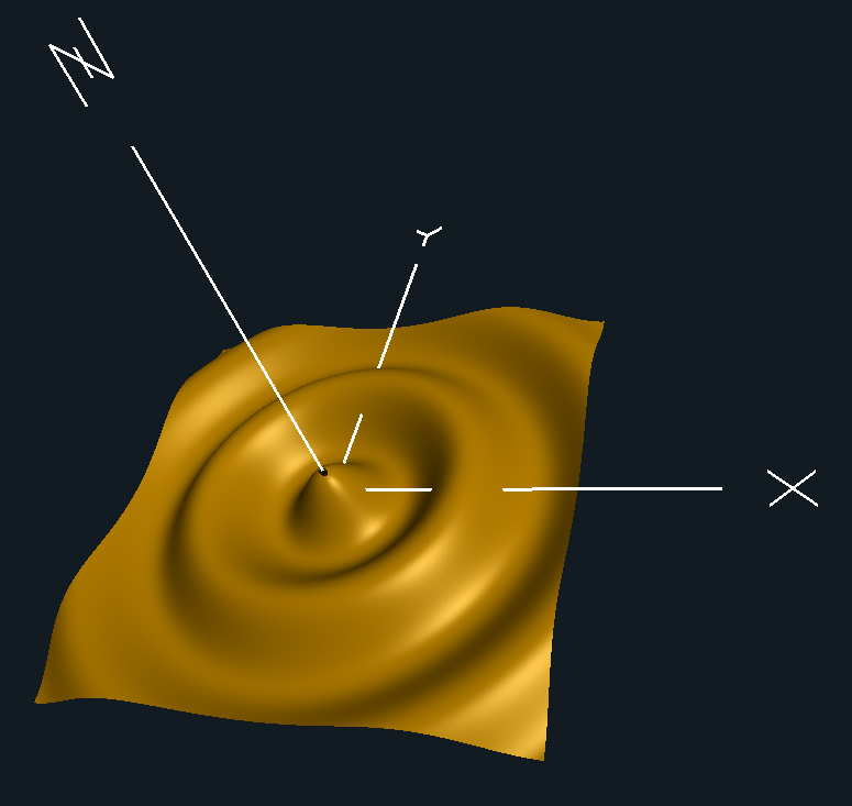
The surface spreads radially across X and Y, rising and falling in Z, and decaying in R. It looks a lot like a rock dropped in a pond.
Z = A * cos(2πBr+C) * e-Dr
where:
r2 = x2 + y2
and:
| Variable: | Controls: |
|---|---|
| A | Amplitude |
| B | Period |
| C | Phase shift |
| D | Decay rate |
In the expression e-Dr, "e" is the natural exponential which is approximately equal to 2.71828 and is used in so many scientific and computer graphics programs that it has its very own function to implement it: exp( -D*r ).
The normal vector for lighting is formed by taking the cross product of tangent vectors.
The tangent vectors are formed like this:
vec3 Tx = vec3(1., 0., dzdx );
and
vec3 Ty = vec3(0., 1., dzdy );
so we need to differentiate the equation to get dzdx and dzdy.
Unfortunately, x and y don't explicitly appear in the Z equation,
so we can't differentiate with respect to them.
But, using the calculus chain rule:
dzdx = dzdr * drdx
dzdy = dzdr * drdy
Now we just need drdx and drdy.
Given that:
r2 = x2 + y2
then:
2r(drdx) = 2x
2r(drdy) = 2y
so then drdx and drdy will be:
drdx = x/r;
drdy = y/r;
(If you care, x/r and y/r are actually the cosine and sine of the horizontal angle around the ripple.)
So, now differentiate the original equation like this:
float r = sqrt(x2+y2)
float dzdr = A * [ -sin(2.*π*B*r+C) * 2.*π*B * exp(-D*r) + cos(2.*π*B*r+C) * -D * exp(-Dr) ]
Then do this:
dzdx = dzdr * drdx
dzdy = dzdr * drdy
Then do this:
vec3 Tx = vec3(1., 0., dzdx );
and
vec3 Ty = vec3(0., 1., dzdy );
So, now the normal is calculated like this:
vec3 normal = normalize( cross( Tx, Ty ) );
Then pass it over to the fragment shader as an out vec3 called vN.
Nothing to it, right? :-)
Be sure your video shows this to be the correct normal by rotating your object to show that lighting works correctly.
As the first part of this is displacing vertices, you need to have enough vertices to displace.
If you are using glman, there is a built-in command to get a quad with a lot of vertices:
QuadXY 0. 1. 128 128
If you are using the API, do something like this:
float xmin = -1.f;	// set this to what you want it to be
float xmax =  1.f;	// set this to what you want it to be
float ymin = -1.f;	// set this to what you want it to be
float ymax =  1.f;	// set this to what you want it to be
float dx = xmax - xmin;
float dy = ymax - ymin;
float z = 0.f;		// set this to what you want it to be
int numy = 128;		// set this to what you want it to be
int numx = 128;		// set this to what you want it to be
for( int iy = 0; iy < numy; iy++ )
{
        glBegin( GL_QUAD_STRIP );
        glNormal3f( 0., 0., 1. );
        for( int ix = 0; ix <= numx; ix++ )
        {
                glTexCoord2f( (float)ix/(float)numx, (float)(iy+0)/(float)numy );
                glVertex3f( xmin + dx*(float)ix/(float)numx, ymin + dy*(float)(iy+0)/(float)numy, z );
                glTexCoord2f( (float)ix/(float)numx, (float)(iy+1)/(float)numy );
                glVertex3f( xmin + dx*(float)ix/(float)numx, ymin + dy*(float)(iy+1)/(float)numy, z );
        }
        glEnd();
}
It is best if this is placed in a display list.
Because we are doing bump-mapping, it must be per-fragment lighting.
The question marks are not glman-isms -- they are asking you to determine good values in those places.
##OpenGL GLIB

Perspective 70
LookAt 0 0 8  0 0 0  0 1 0

Vertex          rock.vert
Fragment        rock.frag
Program    Rock                                 \
                uA <0.0 0.00 1.0>               \
                uB <0.1 0.6 3.0>                \
                uC <0. 0. 6.28>                 \
                uD <0. 0. 2.>                   \
                uNoiseAmp <0. 0. 5.>            \
                uNoiseFreq <0.1 1. 20.>         \
                uKa <0. 0.1 1.0>                \
                uKd <0. 0.6 1.0>                \
                uKs <0. 0.3 1.0>                \
                uShininess <3. 10. 1000.>       \
                uLightX <-20. 5. 20.>           \
                uLightY <-20. 10. 20.>          \
                uLightZ <-20. 20. 20.>          \
                uColor {1. .7 0. 1.}            \
                uSpecularColor {1. 1. 1. 1.}

QuadXY  -0.2  1.  128 128
Note that you need to break the quad down into many sub-quads (the "128 128" above) so that there are enough vertices to create a smoother displacement function.
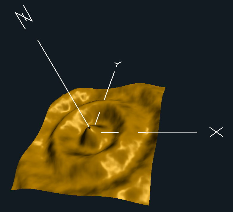
You've determined the normal. Now you want to perturb it in a seemingly random, yet coherent, way. Sounds like a job for noise, right?
Use the noise texture capability to get two noise values. These will be treated as an angle to rotate the normal about x and an angle to rotate the normal about y. Allow the variation of two more uniform variables: uNoiseAmp and uNoiseFreq.
        vec4 nvx = texture( Noise3, uNoiseFreq*vMC );
	float angx = nvx.r + nvx.g + nvx.b + nvx.a  -  2.;	// -1. to +1.
	angx *= uNoiseAmp;

        vec4 nvy = texture( Noise3, uNoiseFreq*vec3(vMC.xy,vMC.z+0.5) );
	float angy = nvy.r + nvy.g + nvy.b + nvy.a  -  2.;	// -1. to +1.
	angy *= uNoiseAmp;
where vMC are the vec3 model coordinates passed over from the vertex shader.
(You could also get the noise from a 2D noise texture using (s,t).
Rotate the normal like this:
vec3
RotateNormal( float angx, float angy, vec3 n )
{
        float cx = cos( angx );
        float sx = sin( angx );
        float cy = cos( angy );
        float sy = sin( angy );

        // rotate about x:
        float yp =  n.y*cx - n.z*sx;    // y'
        n.z      =  n.y*sx + n.z*cx;    // z'
        n.y      =  yp;
        // n.x      =  n.x;

        // rotate about y:
        float xp =  n.x*cy + n.z*sy;    // x'
        n.z      = -n.x*sy + n.z*cy;    // z'
        n.x      =  xp;
        // n.y      =  n.y;

        return normalize( n );
}
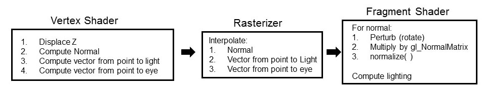
After rotating the normal, multiply it by the gl_NormalMatrix and normalize it:
vec3 n = RotateNormal( angx, angy, vN );
n = normalize(  gl_NormalMatrix * n  );
| Feature | Points |
|---|---|
| Correctly show the effect of changing uA, uB, and uD
(You can hardwire uC to zero if you'd like.) | 30 |
| Correctly show the effects of changing uNoiseAmp | 15 |
| Correctly show the effect of changing uNoiseFreq | 15 |
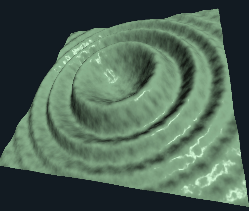
| Use per-fragment lighting to show that you have computed the un-bump-mapped normals correctly | 20 |
| Use per-fragment lighting to show that you have computed the bump-mapped normals correctly | 20 |
| Potential Total | 100 |