ODOT Pipe Ramming Research
Pipe ramming is a simple technique of non-steerable trenchless pipe installation used primarily in horizontal applications in which a ramming tool (an encased piston) is used to drive a pipe or culvert into the ground with high frequency, percussive blows. Compared to conventional, trench cut and cover methods, pipe ramming allows the placement of pipes through highway embankments or other earth structures without long excavation durations, back-filling, road or rail closures, traffic delays, detours, loss of access to homes and businesses. Despite its successful application for some years, little fundamental research on the mechanics of pipe ramming installation has been conducted. The objectives of the OSU pipe ramming project, a collaborative effort between Oregon State University, the Oregon Department of Transportation, and the Oregon and Southwest Washington Chapter of the National Utility Contractor Association (NUCA), is to develop detailed, data- and theory-supported methods to design and specify the installation of pipes and culverts using pipe ramming.
This research was made possible in part by the outstanding collaborative effort of a number of contractors and suppliers, members of NUCA. Oregon State University gratefully acknowledges the effort of:
Oregon and Southwest Washington Chapter, NUCA
Armadillo Underground (Auger rig and tracks, freight, lubricant pumps, labor)
Gonzales Boring & Tunneling (115ft - 42in pipe, welding materials, labor)
J W Fowler Construction (24in Grundoram, air compressor, labor)
Moore Excavation (16in Vermeer Hammer)
Emery & Sons, Inc. (Test site, generator, pumps, labor)
Peterson Machinery Co. (CAT Excavation Equipment)
Wyo-Ben, Inc. (Lubricant, labor)
RDO Equipment (Various small equipment, labor)
An instrumented test pipe was driven in the Summer of 2010 as part of the Pipe Ramming Research. Below are photos showing some of the work associated with the test ram.

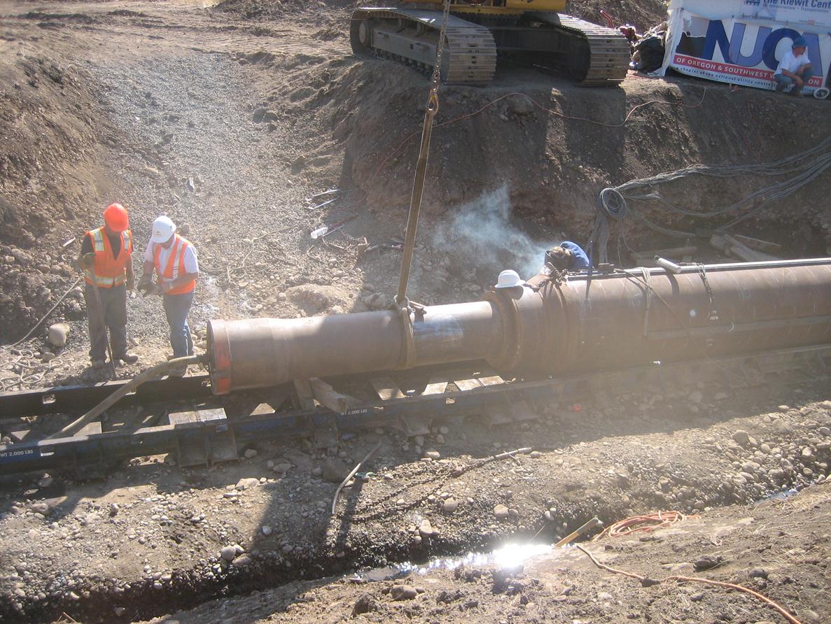
Welding in preparation for ramming with the 24in Grundoram hammer (donated by J W Fowler, Inc.) to drive the final 20ft section of 42-inch diameter pipe, at the Salem, OR test site.

Undergraduate Research Assistant Mitch Madsen prepares the surface of the test pipe for resistance-type strain gages. Approximately 2 miles of wiring was used to connect the pipe to a 100-channel automatic data acquisition system in order to measure pipe strains during ramming.

LEFT: High frequency sampling strain gages and accelerometers, used in pairs, were used to measure the stress waves delivered from the pipe hammer to the pipe. This technology, adapted from dynamic pile testing, allows the instantaneous assessment of soil load on the pipe, installation stresses, and energy transfer. RIGHT: A representative of RMDT, Inc., observes the energy transfer in real time.

LEFT: Prior to starting the test ram, a T1 cutting shoe was welded to the pipe. Cutting shoes form a critical component of a successful ram, and should be selected based on the ground conditions. RIGHT: Energy transfer is optimized by securing the hammer (16in Vermeer hammer, donated by Moore Excavation) to the pipe using chains. The chains must be continuously monitored and tightened, as necessary, to maintain optimum productivity.

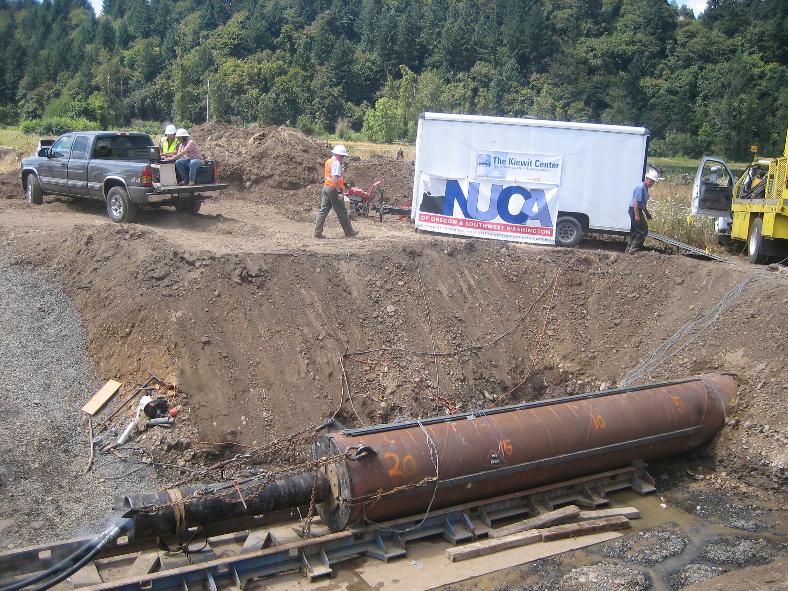
Initiation of the test ram with the 16in Vermeer hammer. The pipe hammer is comprised of a double-acting pneumatically driven piston, delivering up to 240 blows per minute.

Lubricant (donated by Wyo-Ben, Inc.) was used during segments of the test ram to evaluate the reduction in casing resistance along the pipe. LEFT: Batch mixer and pump (donated by Armadillo Underground) used to deliver lubricant to pipe. RIGHT: Evaluation of lubricant viscosity to ensure proper lubricant mixing.


