Toward the Ideal
Mechanical Engineering
Design Support System[1]
David G. Ullman, n
Professor of Machine Design
Department of Mechanical
Engineering
Oregon State University
Corvallis, Oregon, 97330
541-754-3609, ullman@engr.orst.edu
1. Introduction
This paper is a summary
summarizes
theof progress made toward
the development of the ideal mechanical engineering design support system. For nearly 30 years, computer
aided design (CAD) systems have been touted by their developers as systems that
support engineering designers developing products. It is evident
that CAD systems have had a major impact on how design is
accomplished in the workplace. This being said, there is
amazingly
little formal research on the effects of these systems on the designers and on
the final products[2]. This paper presents a structure for
discussing these effects. In doing so, it summarizes what is
known and what needs to be studied. Finally, it discusses how CAD
systems have evolved to support increasing portions of the activities that are
used to develop products.
Since tThe term
“CAD” emphasizes that the computer is an aid to the human designer, so this
paper is designer-centric. It is based heavily on the activities
performed by designers and the types of information developed by them. In many
ways,
this is an update of two earlier papers, “The Importance of Drawing in the
Mechanical Design Process” [Ullman 90] and “Issues Critical to the Development
of Design History, Design Rationale and Design Intent Systems [Ullman 94]. The latter 1994 paper
developed thirteen outstanding issues that needed to be resolved to realize the
capture and query of engineering design information as a potential for
improving the design process and the reuse of design information.
The foundation for the 1990 paper was the study of the
marks made on paper by five mechanical design engineers of varying backgrounds
and experience. They were each given the initial
specifications for one of two fairly simple, yet realistic, mechanical design
problems taken from professional practice. The engineers were requested to think
aloud as they solved the problems. Their verbal reports, drawings,
and and gestures were video- and audio-tapedaudio taped for a
period of 6‑10 hours. The taped data were then transcribed to
obtain a "“protocol"” of the
design session. Each designer made numerous drawings
during his/her solution of the problem. All of these were on paper. CAD systems were not used in the study
because none of the designers used CAD in their daily practice, and its use
would have added another variable to an already complex experiment.
From the more than 40 hours of data taken, 15 sections
were selected that represented typical conceptual, layout, detail and selection
design for each subject. The 15 sections of protocol data
consisted of 174 minutes of data. This The data was
were
analyzed to explore the observations that drawings are used to:
1. Archive
the geometric form of the design.
2. Communicate
ideas between designers and between the designers and manufacturing personnel.
3. Act
as an analysis tool. Often, missing dimensions and tolerances are calculated on
the drawing as it is developed.
4. Simulate
the design.
5.
Serve
as a completeness checker. As sketches or other drawings are being made, the
details left to be designed become apparent to the designer. This, in effect,
helps establish an agenda of design tasks left to accomplish.
6. Act
as an extension of the designer'’s short-term
memory. Designers often unconsciously make sketches to help them remember ideas
that they might otherwise forget.
The 1990 paper refined and
supported these observations. Additionally, although the subjects did
not use CAD systems, the results suggested that:
1. CAD systems must allow for sketching
input.
2. CAD systems must allow for a variety of
interfaces for the designer. This does not mean more ways to define
a circle, but an effort to match the interface and the image on the CAD system
to that needed by the designer.
3. CAD systems must recognize domain
domain-dependent
features and treat them as entities.
4. CAD tools need to be able to
manage constraints (even abstract and functional constraints) and insure
ensure
their satisfaction, as it is evident that human designers are cognitively
limited in this ability.
Since that paper was written, CAD systems have matured and
have addressed, at least to some degree, all four of the conclusions. However, even the most recent
systems are a long way from the ideal mechanical engineering design support
system. In this paper, the ideal system will be
described and progress toward this ideal discussed.
2. A model Model of Design Problem Solving
It may some day
be possible for a designer to put on a “thinking cap” that can take his/her
thoughts and and develop develop a
hardware representation. Research on understanding cognitive
processes, CAD, and and rapid
prototyping are is certainly moving that direction. This
ideal implies that we can formulate concepts in our heads that are sufficiently
well well-formed to warrant hardware. It also assumes that CAD systems are
sufficiently developed to take our thoughts and manage the evolution of parts
and assemblies. To make this
possible, CAD
system development will require an understanding of the
cognitive workings of designers so that the transition from thought to
representation is possible.
To explore what is known about this link, consider the
relationship between the human problem solver and the external environment
shown in Figure 1.
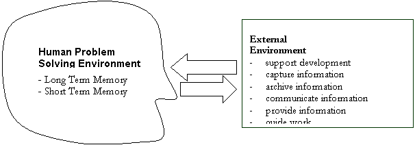
Figure
1. The Problem Solving Environements
This figure is based on the model developed by Newell and
Simon [Newell 72] and is called the Information Processing System
(IPS). The figure is a simple "“map"” of where
information about the design is developed and stored. It is divided
intoThe figure shows an internal, human problem
s-solving
environment (inside the mind of the designer) and an external environment
(outside the mind of the designer). Within the designer, there
are two locations corresponding
to the two different kinds of memory: short-term memory (STM) and long-term
memory (LTM). External to the designer, there are
many "“design storage locations" ” including
graphical representation media such as pieces of paper and CAD tools, as well
as other media such as textual notes, handbooks and colleagues. Each "“location"” has certain
properties that affect how it can be used in design.
Detail on the characteristics of the STM,
and the LTM is based on Newell and Simon'’s model
[Newell 72], ]. Ethe
extensions have been made to it forof it to
visual imagery [Kosslyn 83, Kosslyn 85, Kosslyn 94] and the efforts have been made to
codify it [Anderson 83]. It must be realized that the contents
of the model given here are not fully agreed to in the cognitive psychology
community, but they are certainly secure enough to provide a basis for
discussing the role of CAD in mechanical design.
2.1 The Short Term Memory
Short-term memory is very fast and powerful. The contents of the STM are the information we are aware of, our
conscious mind. All design operations (e.g. visual
perception and drawing creation) are based on information in short-term memory. Unfortunately, the STM has limited
capacity. Studies have shown
that it is limited to approximately seven cognitive units or "“chunks"” of
information. During design, these chunks are visual images of forms,
information about function, mental models of fit, steps to represent an idea in
a CAD system or other discrete pieces of information. Although limited in
capacity, the STM is a fast processor with processing times on the order of 100
msec [Card 83].
2.2 The Long Term Memory
The long-term memory, on the other hand, has essentially
infinite capacity, but access is slow. Access to long-term memory is also not
direct. Instead, mMemories
must be triggered by some cue or retrieval strategy based on information in
short-term memory. During design, parts of the design are
stored in long-term memory. These are relatively easy to cue
because, at any time, currently important parts of the design are in short-term
memory and can act as pointers for the knowledge in the long-term-memory.
2.3 External Environment
In the experiments run in 1990 [Ullman 90], it was
clear that many drawing actions were not to document the results of the design
activity but were part of the design process itself. If the subjects could have performed
these activities in their heads they would have done so without making the
sketches, notes and calculations on paper. Thus, it can
beis concluded that the external environment is
often used as an extension of the STM and LTM. It is critical that the media
used in this environment support the designer’s cognition. Itemizing the match or mismatch between
the media and human cognition is one of the objectives of this paper.
T.
The
approach taken in this paper is to first describe the types of information
managed, (Section 3, ) and then
discuss the activities performed by the external environment supporting the
designer, (Section 4). The types of information and activities
are developed in terms of the capabilities of an ideal system. Each sub sub-section
begins with statements about what the ideal engineering design support system
should do. Supporting information follows these
statements. Next, there is a description of how
paper-and-pencil, 2-D CAD systems, solid-modeling systems, parametric systems
and other support tools meet the ideal. Each subsection concludes with the opportunities
for improvement.
3. Information Managed by an Ideal Mechanical Engineering Design Support System
Mechanical engineers manage a broad range of information. In this section, the various types of
information will be itemized beginning with the most basic and progressing to
the most demanding.
3.1 Form, Fit and Function
The ideal engineering
design support system should:
1. Allow designers to work
from desired function to the other types of information.
2.
Allow designers to flexibly work on the architecture, shape,
fit and function of parts and assemblies.
The mechanical design community has traditionally thought
in terms of form, fit and function. Figure 2 shows the interplay among these
basic types of information that describe the product being designed. Generally, the reason for the object
being designed is to fulfill some desired functions. The form of the parts and assemblies,
and the fit between them, are
dependent on
the desired function of the product. Thus, the ideal system should allow the
designer to work from function to form and fit.

Figure 2. The Basic Types of
Mechanical Design Information
The term “form” actually implies both the architecture and
the shape of parts and assemblies, (Figure 3). The term “architecture” has come to
mean the skeletal structure that maps the function to the form. Architecture is the “stick figure” that
can be easily manipulated and changed before the shape is refined. Shape implies the geometry that adds
body and detail to the architecture. Often designers first develop the
general architecture of the object being designed, then add details about shape
and fit.
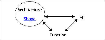
Figure 3. The Basic Types of
Mechanical Design Information with Form Refined
Where we are
today
Engineers generally work from the function of a system, to
the architecture of an assembly, to the shape of parts. Function occurs primarily at the
connections or fits between the parts in an assembly. In other words, function is developed
in assemblies. This being said, CAD systems have
primarily supported the form or geometry development of parts.
Paper-and-pencil allows easy sketching of architecture
with stick figures and their evolution to components. Paper-and-pencil also supports limited
function modeling through sketching actions that show motion or flow in
assemblies [Herbert 87, Kuffner 91].
Both 2-D CAD systems and paper-and-pencil are limited to
simple input of line segments to represent the edges of components. Solid modeling systems are still component
component-oriented
even though they support the representation of edges, surfaces and solids. Parametric systems greatly improved the
modeling of form with the limited ability to model fits and assemblies.
Future systems need to help the designer visualize
function before geometry is fully defined. Computer systems are allowing better
representation of function, e.g. kinematic, dynamic, fluid flow and virtual
reality systems. With the continued development of computer
support tools, the ability to work from function to form will continue to
evolve.
CAD systems to date have been part part-driven. Parts are developed and then fitted
together to make an assembly. The contributions of the layout drawing
have not been well well-supported. Parametric systems have begun to move
to a more natural flow, but parametric modeling requires the designer to plan
ahead of time the geometric constraint relationships that define the part. Many parametric systems refer to the
ordering of the constraints as the design intent. This methodology, while moving toward
the ideal,
does not well support the designer as the planning needed adds burden, and the
ordering may not be known initially and may change during the development. Further, “design intent” as used in
parametric systems is too limiting (see discussion of design intent below).
Opportunity
Extend CAD systems to allow the designer to develop the
architecture of parts and assemblies to fulfill needed function. They must allow the designer to work from the architecture to the
shape and fit of the components themselves. This will require work with
abstractions of parts and assemblies and building the geometry of objects from
their architecture and interfaces with other objects.
3.2 Material and Manufacturing
The ideal engineering
design support system should:
3. Integrate the
manufacturing and assembly practices and common material usage of the company
or its vendors.
One of the cornerstones of Concurrent Engineering is the
integration of the development of the product and the processes that support
the product. Key among these processes are those
used to manufacture the parts and assemble them. These activities are also
dependent on the selection or development of
the best materials for the product. Thus, as shown in Figure 4, the basic
form (architecture and shape), fit and function need to be tied to materials,
manufacturing and assembly.
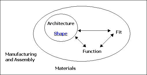
Figure 4. The Basic Types of
Mechanical Design Information with Manufacturing, Assembly and Materials Added
Where we are today
Currently, there are systems that aid in development
of injection molds and sheet metal parts. However, for most manufacturing and
assembly methods, only text notes have supported this non-geometric
information.
Opportunity
Extend CAD systems to provide the designer with
information of about anticipated material and manufacturing
methods. This needs to be personalized as each
company and vendor has certain materials, and and manufacturing and assembly methods that are
standard and well well-known. Knowledge about these should be easily
available to the designer to aid in the development of parts and assemblies.
3.3 Cost
The ideal engineering
design support system should:
4. Support the engineer so
s/he is aware of the effect of each feature change on cost as it is generated.
 The
cost to make the object being designed is not a part of its description, yet it
is a major factor in all design considerations.
The
cost to make the object being designed is not a part of its description, yet it
is a major factor in all design considerations. It is shown in Figure 5, as closely
tied to the material used and the manufacturing method and through these
indirectly to the function and form. Often there is a disconnect during the
design process between drawing a component and establishing a cost for it. In many companies, the engineer draws a
component and sends it to another group for cost estimation. The time lag in this process does not
match what is needed for efficient design.
Figure 5. The Basic Types of
Design Information Plus Cost
Where we are today
Cost estimation has not been well well-supported
by any type of system. Some DFA (Design for Assembly) systems
can estimate for
cost,
for but these are not integrated with
part representation in a CAD system.
The cost of a component is based on: the major dimensions
of the component, the architecture of the component, the tolerances and surface
finish needed, the number to be made, the material used, the machines used in
the manufacturing process, and and labor and
machine rates[3]. The first three items can be directly
developed from the geometry and other notation commonly put on a drawing. The number to be made can be input by
the designer. Since every organization has a palette
of materials and manufacturing processes that are used for most products, these
should be integrated with the geometry through a database. Then, the
material properties, material costs, machine costs and labor rates for the
organization could be linked with the geometry. With this information a cost estimate
within 10% of the actual can be developed and updated with changes made in the
geometry or other variable.
Opportunity
CAD systems need to generate a running update of costs as
parts and assemblies as changed – in real time.
3.4 Requirements
The ideal engineering
design support system should:
5.
Support the relationship between the
requirements and the development of the product.
The requirements (here the term is used synonymously with
constraints, specifications or goals) for a part or assembly are a type of
information that does not describe what is being designed, but the limitations
and targets on it. As such, it is
critical information. It At is
shown in Figure 6. T, there are
requirements on all the other types of information shown in the
figurepreviously discussed. Traditionally, engineers have done a
poor job at developing requirements for products.
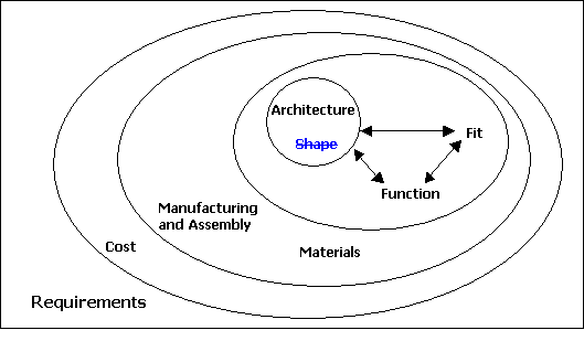
Figure 6. Requirements on the Basic Types of Design Information
Where we are today
One of the best practices currently used to develop
requirements in industry is Quality Function Deployment, (QFD) [Clausing
94, Ullman 97]. Many companies use the results of this method to directly feed
requirements to the development of components and assemblies. Admittedly, many of
the requirements developed with the QFD are for function, ; however, there are
always many constraints on both function and geometry that drive the
development of parts and assemblies. To date, this is not well integrated with CAD
systems.
Stauffer [Stauffer 87] showed that as the design process
moves from conceptual through layout to detail design, the source of
constraints moves from those imposed from outside the control of the designer
to those based on previous design decisions. This implies that not only should
requirements like those developed using QFD QFD-type
methods be integrated, but also the reasoning behind earlier decisions needs to
be supported. This will be further discussed in the
section on design intent.
Opportunity
CAD systems need to integrate requirements and constraints
into the development of parts and assemblies.
3.5 Issues and Plans
The ideal engineering
design support system should:
5. Support the development,
following and updating of plans.
6. Support the management of issues not
planned for.
Where all the types of information described so far
represents the artifacts being designed and the
requirements on them, the following types of information represent the process
through which the artifacts are developed. The importance of the process has been
a concern in industry since the early 1980s and an area of research since the
mid 1980s. The tie between product and process is
a major part of concurrent engineering. In the late 1990s, this
concern has been brought into prominence with the development of interest in
Integrated Product and Process Development, (IPPD),
the successor to concurrent engineering.
Traditionally, the product design community has
addressed addresses the
design process in terms of the tasks to be completed to develop a new product. These tasks are focused on specific
design issues that can be planned for in the development of the product. However, many issues arise during the
design of a product that can not be planned for. This is especially true during the
development of new products or during the use of new technologies. Figure 7
shows that issues and plans address all types of requirements and product
information.
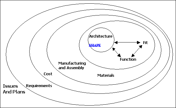
Figure 7. Issues and Plans for Design Information Development
Issues or tasks in product design require the designer to
develop new information. One of the first experiments aimed at
understanding human information processing during design tasks [Stauffer 91]
showed that over two two-thirds of the strategies used by the
design engineers during the development of new products were searches through
design space. Searches imply that there is a range of
potential solutions to every issue and that the designer must look at several
of these alternative solutions to develop one that is satisfactory. Searches
strategies are well studied by the Artificial Intelligence community. Three types of strategies defined by
computer scientists and identified in the cognitive study were “generate
and test”,
“generate
and improve”,
and and “means ends analysis”. In each search type, the designer
develops and refines the alternatives and compares them to the requirements
until some satisfactory choice had been made in the time available. Based on these findings, in order to
support designers, systems must not only track the completion of planned work,
but must also support the development and management of multiple alternatives
for all issues addressed.
Where we are today
Project planning and change management has always been a
large part of engineering management. Product Data Management,
(PDM, ) systems
have made large strides toward integrating the actual design work with what was
planned. These systems are still maturing.
Opportunity
Computer support tools need to continue evolution to
assist the engineer in developing the product and the process in an integrated
fashion.
3.6 Intent
The ideal engineering
design support system should manage all the previously defined types of
information in a
database plus:
7. Support information
about problems or issues addressed (e.g. business issues, planning issues, and and
artifact design issues).
8. Support information
about arguments for or against alternatives (e.g. qualitative discussion,
quantitative
analysis, rules, and and
standards) based on
requirements.
9. Support information
about the decisions reached.
A number of authors have explored the concept of recording
a design history. Nearly fifteen years ago, Mostow
stated that there was a growing consensus in the artificial intelligence
community that "“An idealized design history is a useful
abstraction of the design process"” [Mostow 85]. In the late 1980s, this author and his
colleagues built an object object-oriented
database that organized information about the design of a simple mechanical
system [Ullman 91a, Chen 90, 91]. This database could be queried about
the evolution of constraints and the effect of decisions on the artifacts being
developed.
Since Mostow, the artificial intelligence community has
been active in developing design rationale systems. A workshop held in 1992 [Lee 92] that
defined the term "“rationale"” as "“an
explanation that answers a question about why an artifact is designed as it is."” Baxter [Baxter 90], in his thesis,
refines the definition, : "“Design
rationale: An information structure that justifies how the implementation
(consequences of the design selections) satisfies its specification."” This
definition emphasizes the structure of the design information and tracking the
relation of decisions back to the specifications.
Another community, which is organized around development
of the STEP IV standard, uses the term design intent. Their use of design intent refers to
the cause and effect relationships among product data. In an unpublished document, a STEP IV
researcher states: "“Generally,
the term intent means the purpose or plan for performing activities. During product design, these
activities transform a set of requirements to the final specifications for
production. In a basic sense, the intent is the
blueprint for the evolution of the requirements into the production
specifications. This blueprint not only has information
about the development of the geometry, but also on the evolution of the product
function and behavior, the rationale underlying design decisions,
and and the influence of business activities."”
In the CAD community, the term “intent” is used to describe the
ordering of geometric constraint equations in a parametric system. This ordering defines the geometric
dependency needed by the system in order to make changes and is not necessarily
the cognitive ordering that was followed by the designer in the development or
refinement of the part or assembly.
Finally, in some business literature, the term corporate
memory is used to emphasize the feeling that the information managed is
beyond that associated with the traditional artifact as it includes business
information as well. In the results of the first CERC Workshop
on Enabling Technologies [Nichols 92], the discussion on corporate memory was
in terms of design histories and rationales.
Supporting full design intent information may even be more
complex than storing what has been generated during design. Gruber [Gruber 93] claims that it is
not sufficient just to capture, store and retrieve the same information. He observes: "“Rationales
(intents) are constructed and inferred from stored information rather than as
complete answers."” In other words, design intent systems
may have to answer questions that require information different than that
captured. The questions that arise during query
may not be answerable with only the information of the original design. This implies that the data must be
structured during capture or storage so that answers can be developed to needed
questions.
Design intent systems must record and manage information
that shows why and how a decision was made about each issue addressed. As shown
in Figure 8, a design intent system needs to support all the types of
information previously developed and store this information in an easily
indexable database.
Where we are today
To capture, store and allow query of the design
information is a challenging research area [Ullman 94]. To a limited degree, PDM systems are
beginning to manage some of the needed information. However, these systems tend to be
oriented toward information that is well refinedwell-refined
and not evolutionary information. Further, these systems do not have a
formal mechanism for managing information about argumentation leading to
decisions.
Parametric and
variational systems allow for design reuse. Thus, it is easy to find the answer
to queries about the aeffect of form
changes and sensitivities. In this manner, these systems have captured some of
the intent behind the information modeled. One limitation of these systems is
that they can only be used with geometric decisions and decisions about
behavior that can be geometrically modeled. Additionally, these systems do not
model the actual decision structure. They only
record
but the order initially
anticipated to give the system necessary geometric reasoning. If the value of a
parameter (i.e. the length of a part) is queried, parametric systems will give information
on this length’s dependency on other dimensions of the part. However, it does
not give the rationale for the relations or the arguments for the current
value.
A number of CAD
companies have begun to offer design notebooks that allow the designer to put
notes about the evolving products. These notebooks are the first step in
supporting needed activities and information. However, it is believed that
additional structure and indexing will be necessary to achieve useful design
rationale support systems[4].
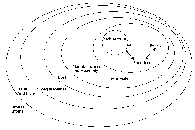
Figure 8. Design Intent
Parametric and variational
systems allow for design reuse. Thus, it is easy to find
the answer to queries about the affect of form changes and sensitivities. In this manner, these systems have
captured some of the intent behind the information modeled. One limitation of these
systems is that they can only be used with geometric decisions and decisions
about behavior that can be geometrically modeled. Additionally, these systems do not model the
actual decision structure but the order initially anticipated to give the
system necessary geometric reasoning. If the value of a
parameter (i.e. the length of a part) is queried, parametric systems will give
information on this length's dependency on other
dimensions of the part. However, it does not give
the rationale for the relations or the arguments for the current value.
A number of CAD companies
have begun to offer design notebooks that allow the designer to put notes about the evolving products. These notebooks are the
first step in supporting needed activities and information. However, it is believed
that additional structure and indexing will be necessary to achieve useful
design rationale support systems[5].
Opportunity
There is great potential in this area for improving the
design process and the reuse of information. CAD systems have begun to capture and
manage the needed information.
4. Ideal Mechanical Engineering Design Support System Activities
There are seven activities that the external environment
provides to the
designer regardless of information managed and the media used. These activities
serve as dimensions for measuring the external environment’s ability to aid the
designer. The activity discussion is based on that presented in “Issues
Critical to the Development of Design History, Design Rationale and Design
Intent Systems” [Ullman 94].
4.1 Support information development
The ideal engineering
design support system should support the manipulation of the different types of
information and:
10. Match the speed of the
Short Term Memory during information development
11. Add no cognitive burden
while supporting information development.
Design is the evolution of information punctuated by
decisions. The types of information that are
developed during the design process represent both the product being designed,
the process by which it is being designed, and and other processes in the life of the
product such as manufacture, distribution and retirement. This information does not spring into
being fully formed but evolves through a series of problem solving episodes. Based on cognitive studies, the average problem-solving episode is
about one minute in duration [Ullman 88]. In a majority of these episodes, a micro
problem is addressed that has as its goal the development or refinement of
information. [Stauffer 91]. In each
of these, a number of alternatives are considered and judged relative to some
criteria. The resulting decision can be one of
many options: adopt a single alternative, develop new criteria, refine the
evaluation, etc.
Support for information development is to act as an
extension of the short-term memory. To accomplish this, the
external memory must match the speed of the STM. Engineers are notorious for not being
able to think without making "“back-of-the-envelope"” sketches of
rough ideas. Sometimes these informal sketches serve
to communicate a concept to a colleague, but more often they just help the idea
take shape on paper by extending the STM. Dan Herbert in Study Drawings in
Architectural Design: Applications for CAD Systems [Herbert 87] considers
the use of sketches (study drawings to architects) in the solution of
architectural design problems. He defines "“study drawings"” as "“informal,
private drawings that architectural designers use as a medium for graphic
thinking in the exploratory stages of their work."” Architects often make these study
drawings in the borders of or adjacent to their formal drawings. In Herbert'’s theory,
sketches are used because they provide an extended memory for the visual images
in the mind of the designer. Since sketches can be made more rapidly
than formal drawings, they allow for more facile manipulation of ideas. Furthermore, sketches
allow the information to be represented in various forms such as differing
views or levels of abstraction. Thus, he calls sketches graphic metaphors for
both the real object and the formally drafted object under development. In fact, Herbert
claims that sketches are a principal medium of external thinking. Thus, the external media must match the speed of the STM. It also should support the manipulation
of the ideas.
Since humans are already cognitively limited by a STM that
can only manage seven chunks of information, the media of the external memory
must provide aid with minimal cognitive baggage. For each additional chunk required by
the external media is one less for problem solving. For example, if it takes part of STM to
draw a sketch for a new idea using a CAD system, then the idea represented
will, by necessity, be less complicated [Springer 90].
Where we are now
Springer compared an early version of AutoCAD (2.6) to
work on a drafting board. The results showed that CAD took nearly
twice as long to produce a comparable design because “ a
bottle neck in using the CAD-system forces
the subjects to concentrate on the use of the CAD dialog and to neglect the
design task.” This result held regardless of
increased CAD experience. Although this research is dated, the
result is not. During the use of CAD systems, icon and menu selecting add
unneeded steps to creating an image. A current best selling parametric
system has menus up to 5 levels deep that are needed to do
many operations. These added steps
are add an extreme cognitive burden to both the
novice and expert user.
One part of the cognitive research discussed in the
introduction of this paper [Ullman 90] focused on the marks on paper designers
make during the design process. In the protocol sections studied, the
average length of time to make a mark on paper was 7.3 seconds with a standard
deviation of 7.8 seconds. The 363 marks-on-paper studied were
divided into "“draw"” marks and "“support"” marks. These
are further refined into "“sketch"” and "“draft"” marks,
and and "“text"”, "“dimension"” and "“calculate"” marks
respectively. Thus, there are five types of marks-on-paper. They are defined
as:
·
·
Sketch:
Drawings of features made free hand. 48% of marks in paper. Sketching on paper is not the same as
sketching on the computer using a CAD system.
·
·
Draft:
Drawings made with mechanical devices. 24%
·
·
Text:
Letters, words or numbers that are not part of a dimension on a drawing
and not part of a calculation. 9%
·
·
Dimension:
Dimensions or dimension lines on a drawing (either a sketch or a draft). 14%.
·
·
Calculate:
Equations and answers to calculations. Combines constraints or design
proposals to derive new information. 5%
There was some debate as to how to differentiate between
sketch and draft. There are two measures to consider: (a)
the use of instruments and (b) whether or not the drawing was to scale. Consistency with traditional college
graphics texts suggests that the criteria should only be the use of instruments
as defined above. All of the subjects had instruments at hand.
However, some subjects chose to make their scale drawing free free-hand. It would seem that they felt that it
was easiest not to use the instruments. The differentiation between sketch and
draft is made even clearer by considering when in the design process the
drawing was made. When the subjects were trying to conceptualize the design,
100% of the drawings were sketches. Later in the design, during the layout
and detail phases, this drops to 52% as some of the subjects used instruments
to draw their refined design while others continued to sketch.
Over, 67%
of the drawings were sketches. An argument could
be made that mMany of
these sketches could have been made using drafting equipment or on a CAD
system. A counter argument is thatBut, with
the average length of these sketching actions at less than 8 seconds, the use
of instruments or CAD could have slowed the drawing action to the point that
the cognitive problem solving would be impaired. Thus, even the use of simple drafting
instruments added sufficient cognitive burden that they were not used during
conceptual design.
Opportunity
A goal of CAD vendors should be to develop systems that
work at the rate of cognition. Such systems would have virtually no
menus. A research project with this goal was
undertaken in 1989 [Hwang 90]. The resulting system could infer
complex geometry solids from simple sketching motions. Although this may not be viable for a commercial
system, five layers of menus are not viable for a system that matches human
abilities.
4.2 Capture, Archive and Query information
The ideal engineering
design support system should:
12. Capture all types of
information with single entry.
13. Archive all the types of
information so that design intent can be readily recovered.
14. Support designer query
about the design intent for all types of information.
The three activities necessary for a design history or
design intent system are the capture, archiving and query of design
information. Thus, these three are discussed
together.
Design information is captured in the external
environment. This information may be discarded as with traditional paper layout
drawings, white board drawings and many notes, or it may become part of the
product archive. Typically, only information
about the geometry of the final parts and assemblies are archived. Many engineers also capture information in design notebooks. This information is often only readable
by the engineer who wrote it and is not indexed in any useful way. Captured information forms the basis
for a design intent system.
The external environment also serves to store information
about the product or the process. Typical types of information archived
in the past are, for example: part and assembly drawings,
plans, meeting notes, bills of materials, and and simulation and test results. These types of information generally
give a snapshot of the final product with minimal information about the
decisions that went into its development (the intent). To support the types of information
described above will require an enhancement of the current types of information
stored and a refinement of database technology.
Query is the activity of reviewing design documentation in
an attempt to learn about past activities related to a product or a process
followed. Designers currently working on a
project, reviewing their own past work, or the past work of others often seek
information about both the product’s and the process’s
history. Often this is described as seeking the design rationale, intent or
corporate history [Ullman 94]. Similar to designers, managers usually
want to obtain information at a high level and then have the ability to burrow
down to deeper information as desired. Further, they also want information
about whom is responsible for a given issue on a project, who is working on a
project and the inter-relationships between projects.
Kuffner [Kuffner 91] performed a small set of experiments
to try to determine the value of design information during redesign. In this study, he gave
engineers drawings for a simple product and asked them to make changes. He recorded their work and analyzed it. One of the conclusions of this study
was "“mechanical design engineers are interested
in design information other than that which is contained in standard design
documentation."” Query is often directly related to the
role. Typical roles he found were state
(versions), proposal, requirement and example. Version information included changes
that occurred earlier in the development than those captured by the traditional
engineering change management system.
The designers also sought answers to process questions. These included questions about the
issues faced, the alternatives developed to satisfy the issue, evaluations of
the alternatives and decisions made.
Where we are now
Current CAD systems capture primarily form information. Some systems are adding notebook
features that allow notation and linking to other information. These additions are in their infancy
and are still difficult to query.
Opportunity
This area is seen as one of with the
greatest potential for future design support. Engineers spend a great percentage of their
time recreating prior work or looking for prior information. The ability to capture, archive and
query the full range of design information will have extensive payback in terms
of design efficiency and design quality.
4.3 Communicate information
The ideal engineering
design support system should:
15. Communicate information in the format, level
of abstraction and level of detail needed.
Communicating information among design team members and
managers is an essential part of engineering workflow support. Communication must be across time and
location. Further, many types of information are
used in the support of engineering design, i.e. text, CAD files, analysis
results and the ability to actively run analyses at remote locations,
experimental results, and and photographs.
Additionally, communication must support others who are
in need of the information developed by the engineers. Manufacturing, product support, sales
and other functions need the information from different viewpoints and at
different levels of abstraction and detail.
Where we are now
The Internet has greatly improved the ability to
communicate graphical information among engineers. There are still some limitations due to
difficulty converting data between systems. Various standards have helped but there
is still need for more work on data conversion.
One measure of the efficiency of a system is to count how
many times the same information needs to be entered on paper or in the
computer. The ideal system will have a single
entry. Thus, the best computer support system
should allow a piece of information to be entered once and then be usable by
all parties to support their function in the organization. CAD companies have been aware of this
goal for many years and have been making progress toward it.
Opportunity
CAD vendors need to continue to work on file transfer,
geometric and other standards, and and single entry of information.
4.4 Guide work
The ideal engineering
design support system should:
16. Guide the designer about what to do
next.
During the design process, decision-makers are
repeatedly asking three questions [Ullman 98]:
·
·
AWhat
is the best alternative”?
·
·
ADo
we know enough to make a decision yet”?
·
·
and A What
do we need to do next to feel confident about our decision”?
This last question is a request for guidance. Should the designers [Ullman 00]:
·
·
Develop
more evaluation information?
·
·
Further
interpret and discuss evaluation information?
·
·
Generate
new potential solutions?
·
·
Refine
criteria features and targets?
·
·
Negotiate
changes in criteria features and targets, and and their importance?
·
·
Decompose
the issue into sub-issues?
·
·
Reach
conclusion and document result?
Currently, there is no methodology for guidance about
what to do next. Often designers do whatever is easiest,
not what will lead to a better decision. This is compounded in team situations. The guidance addressed here is not the
same as planning. Planning can be done in advance whereas
this is directed at work in progress.
Where we are now
There has been very little work in this area. A forthcoming book, Ten Steps to Robust Decisions: Building Consensus in Product
Development and Business, [Ullman
00],
will address these issues.
Opportunity
Every feature added to the design of an assembly or part
requires many decisions. Much time is wasted making poor
decisions. The opportunities here are great.
5.0 Conclusions
Mechanical design support systems have done much to change
engineering design practice over the last twenty years. Yet computer based systems are weak in
their ability to support many of the activities and types of information
identified in this paper. Further, there is little experimental evidence
on the effect of CAD on the designer. It could be argued that much
in this paper is outside the expectations of what a CAD system is supposed to
do and that PDM systems, planning software, notebooks, material selectors, etc. are
designed to provide these missing functions. It could also be argued that evidence of CAD’s ability to support
the design process is evidenced by its wide use. These arguments depend on expectations. If a CAD system is designed to support
drawing only, then that is all it will support. However, and this is a major point in
this paper, design is more than making drawings. It is a complex human/computer
undertaking and, to date, the computer has only filled a very small segment of
its potential. Future CAD systems need to be mechanical design support systems
and fill all the needs developed in this paper. This is now possible, as previously CAD
systems were developed to meet the computer’s capability. However, computer systems are now very
powerful and well refined. Thus, future CAD development needs to
be driven from the "“D"” and not from
the "“C"” in "“CAD"” where the "“D"” is for
design, or even more appropriately, “D” stands for designer. This will require focused studies of
human designers and their interactions with mechanical design support systems.
References
[Alder 89]
“CAD/CAM: Managerial Challenges
and Research Issues”, P.S. Alder, IEEE Transactions on Engineering Management, VolVol. 36, #3,
Aug 1989, pp 202-215.
[Anderson 83]
The Architecture of Cognition, J.R. Anderson, Harvard University
Press, (1983).
[Baxter 90]
"“Transformational
Maintenance by Reuse of Design Histories" Baxter” Baxter I.,
Ph.D. Dissertation, Information and Computer Science, University of California
at Irvine, 1990.
[Card 83]
The Psychology of Human-Computer Interaction, S.K. Card, T.P. Moran
and A. Newell, Lawrence Erlbaum Assoc. Hillsdale, N.J. (1983).
[Chen 91]
"“A
Computer-Based Design History Tool"”, Chen A.,
Thesis for the Department of Mechanical Engineering, Oregon State University,
July 91.
[Chen 90]
"“Design
History Knowledge Representation and Its Basic Computer Implementation"”, Chen A, McGinnis B. and D.G. Ullman, The
Proceedings
of the Design Theory and Methodology Conference - DTM 90 -, ASME DE - Vol. 27,
Sept 90, pp 175-184.
[Clausing 94]
Total Quality
Development: A Step-by-Step Guide to World-Class Concurrent Engineering, D.
Clausing, ASME Press, 1994.
[Gruber 93]
"“Generative
Design Rationale: Beyond the Record and Replay Paradigm"”, Gruber T.
and D. Russell, KSL 92-59, updated Feb 1993.
[Herbert 87]
“Study Drawings in Architectural
Design: Applications for CAD Systems” ,,” D. Herbert,
Proceedings of the 1987 Workshop of the Association for Computer-Aided Design
in Architecture (ACADIA), ((1987)).
[Hwang 90]
"“The Design
Capture System: Capturing Back-of-the-Envelope Sketches"”, Hwang,
T.S., D.G. Ullman, Journal of Engineering Design, Vol. 1, No. 4, 1990,
pp. 339-353.
[Kosslyn 80]
Image and Mind, S.M. Kosslyn, Harvard University Press, Cambridge
Mass,1980, (1980)).
[Kosslyn 83]
Ghosts in the Minds Machine, S.M. Kosslyn, W.W. Norton Co, ((1983)).
[Kosslyn 85]
Individual differences in mental
imagery ability: A computational analysis, S.M. Kosslyn, J. Brunn, K.R. Cave,
and and R.W. Wallach, Chapter 5 in Visual Cognition edited by S. Pinker,
Bradford Book, MIT Press, pp 195-243 (1985).
[Kosslyn 94] }
Image and Brain, The MIT Press, Cambridge MA, (1994).
[Kuffner 91]
"“The
Information Requests of Mechanical Design Engineers,"” Kuffner, T.
and D.G. Ullman, Design Studies, Vol. 12, No. 1, January 1991, pp.
42-50.
[Lakin 92]
"“Mapping
Design Information"” Lakin F., Baya V., Cannon D., Brereton M., Leifer L, and and G. Toye, AAAI 92 Work shop.
[Liker 92]
“Fulfilling the Promises of CAD”, Liker jJ.K., M.
Fleischer, and and D.
Arnsdorf, Sloan Management Review/Spring 1992, pp 74-86.
[Lee 92]
"“Summary
Report of AAAI '‘92 Workshop on Design Rationale, Lee J.,
Concurrent Engineering Research in Review, Autumn 92, VolVol. 4,
Concurrent Engineering Research Center, UNA, pp 29-32.
[Luczak 91]
“Frictions and Frustrations in
Creative-Informatory Work with Computer Aided Design – CAD Systems”, Luczak et
al, in Human Aspects in Computing, Elsevier, 1991, pp 175-179.
[Manske 89]
“Design Work in Change: Social
Conditions and Results of CAD Use in Mechanical Engineering”, F. Manske and H.
Wolf, IEEE Transactions on Engineering Management, VolVol. 36, #4,
Nov 1989, pp 282-292.
[Mostow 85].
"“Toward Better
Models of the Design Process"”, Mostow J., AI Magazine, 6(1) pp 44-57.
[ Newell
72]
Human Problem Solving, A. Newell and H.A. Simon, Prentice Hall,
Englewood Cliffs N.J. (1972).
[Nichols 92]
"“CERC'’s First
Workshop on Enabling Technologies for Concurrent Engineering"”
, Nichols, D et al, Concurrent Engineering Research in Review,
Summer 92, VolVol. 3, Concurrent Engineering Research
Center, UNA, 14-15.
[Robertson 92]
“Managing CAD Systems in
Mechanical Engineering Design”, D. Robertson and T.J. Allen, IEEE Transactions
on Engineering Management, VolVol. 39, #1, Feb 1992, pp 22-31.
[Robertson 93]
“CAD System Use and Engineering
Performance”, D. Robertson and T.J. Allen, IEEE Transactions on Engineering
Management, VolVol. 40, #3, Aug 1993, pp 274-282.
[Salzman 89]
“Computer-Aided Design:
Limitations in Automating Design and Drafting”, H. Salzman, IEEE Transactions
on Engineering Management, VolVol. 36, #4, Nov 1989, pp 252-261.
[Springer 90]
“Stress and Strain Caused by CAD
Work – Results of a Laboratory Study”, Springer J., et al. In Work
with Display Units 89, Berlinguet L. and Berthelette D. editors, Elsevier
Science Publishers, 1990.
[Stauffer 87]
"“An Empirical
Study on the Process of Mechanical Design"”, Stauffer
L., Thesis for the Department of Mechanical Engineering, Oregon State
University, Sept 87.
[Stauffer 91]
"“Fundamental
Processes of Mechanical Designers Based on Empirical Data,"” Stauffer,
L.A., D.G. Ullman, Journal of Engineering Design, Vol. 2, No. 2, 1991,
pp. 113-126.
[Ullman 88]
"“A Model of
the Mechanical Design Process Based on Empirical Data,"” Ullman,
D.G., T.G. Dietterich, L. Stauffer, Academic Press, AIEDAM, 2(1), 1988,
pp. 33-52.
[Ullman 90]
“The Importance of Drawing in the
Mechanical Design Process,"” Ullman, D.G., S. Wood, D. Craig, Computers and Graphics, Special
Issue on Features and Geometric Reasoning, Vol. 14, No. 2, 1990, pp. 263-274.
[Ullman 91a]
"“Design
Histories: Archiving the Evolution of Product,"” Ullman,
D.G., Proceedings of the DARPA Workshop on Manufacturing, Salt Lake City,
February 1991.
[Ullman 91b]
"“The
Foundations of the Modern Design Environment: An Imaginary Retrospective,
Ullman, D.G., Proceedings of the Workshop on Research in Design Thinking, Delft
University, May 1991.
[Ullman 94]
"“Issues
Critical to the Development of Design History, Design Rationale and Design
Intent Systems"”, Ullman, D. G. and R. Paasch, ASME Design
Theory and Methodology Conference, DTM94, Minneapolis, Sept 1994, pp
249-258.
[Ullman 97]
The Mechanical Design Process, 2nd edition, Ullman,
D.G., McGraw-Hill, NY, (1997).
[Ullman 98]
AWhat
to do Next: Letting the Problem Status Determine the Course of Action@,
Ullman D.G., D. Herling and B. D. =Ambrosio,
Research in Engineering Design, 1997 (9), pp 214-227. Shortened version in Volume 2 of the Proceedings of the International
Conference on Engineering Design, ICED97, Tampere, Finland, Aug 1997, pp 93-99
[Ullman 00]
Ten Steps to Robust Decisions:
Building Consensus in Product Development and Business, D.G. Ullman, in
preparation,
(2000).