
ODOT Research on Torsional Load Transfer of Drilled Shaft Foundations
Drilled shaft foundations offer an excellent alternative for transferring superstructure loads to soil and rock, and are commonly used to support mast arm traffic sign and signal poles. The design of these drilled shafts must provide sufficient capacity to resist the maximum anticipated loads, including lateral and torsional loads, the latter of which generally results from wind gust loading. In Oregon, wind storms have produced a maximum recorded wind gust of 237 km/h, which results in significant drag-type loading on traffic signs and signals. Despite the prevalent usage of drilled shafts, the understanding of the actual torsional resistance provided by drilled shafts is not well established. National codes require that drilled shafts be designed to resist torsional loads but do not provide specific design guidance for computing torsional resistance or allowable displacements (i.e., rotation). This research is being conducteded to help understand the transfer of torsional loads to soil along the soil-shaft interface and provide design guidance to ODOT.
This research was made possible by Oregon DOT Grant SPR-304-701; we also thank PLI Systems, Inc. of Hillsboro, OR, for donating materials and services to install the test shafts.
Please check back for additional links to forthcoming publications on our research. Below, you may browse some of the photos of the full-scale test specimens that provided the basis for the load-transfer measurements.
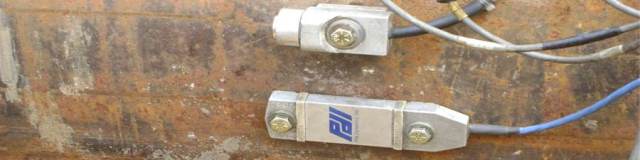
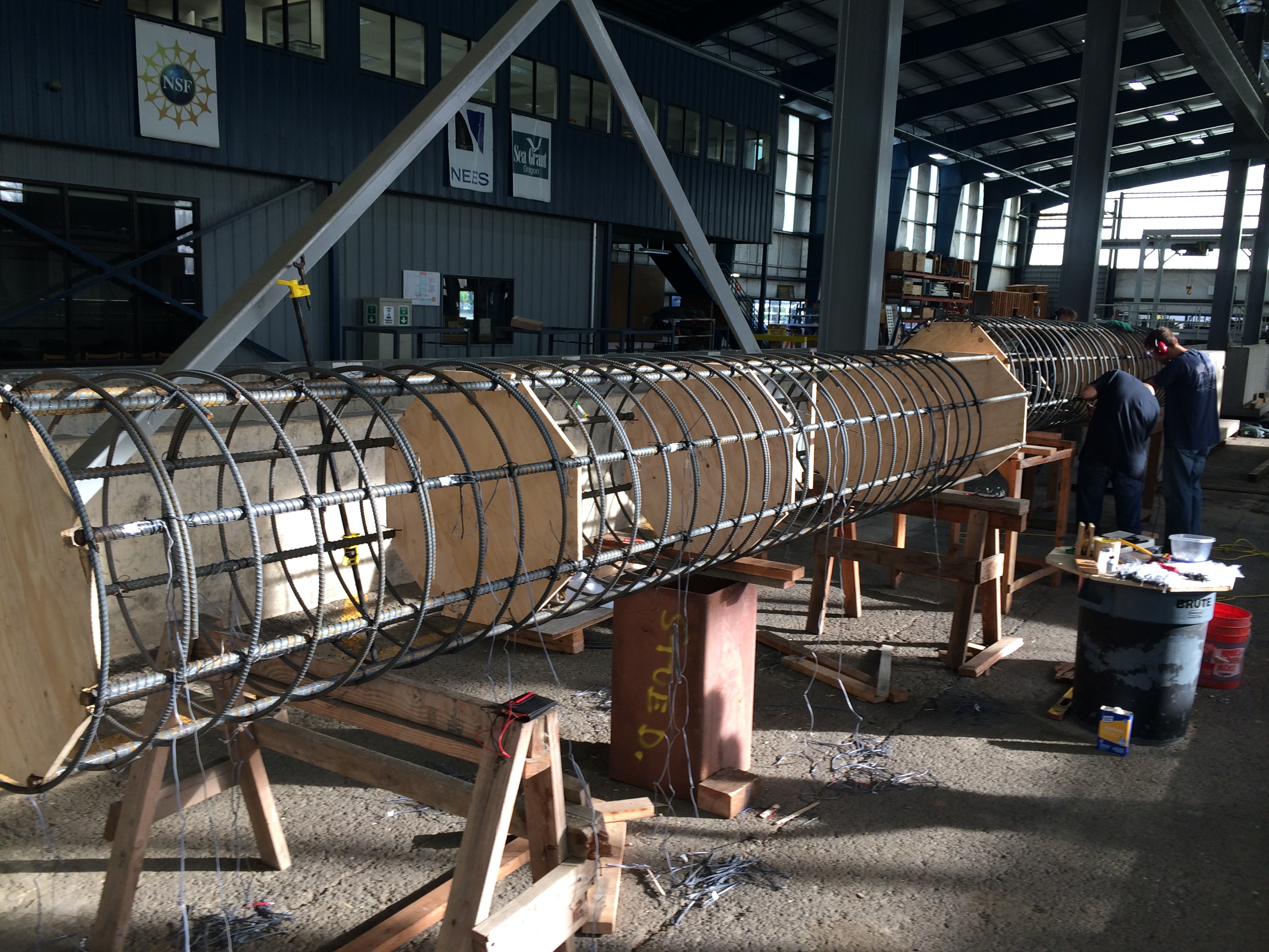
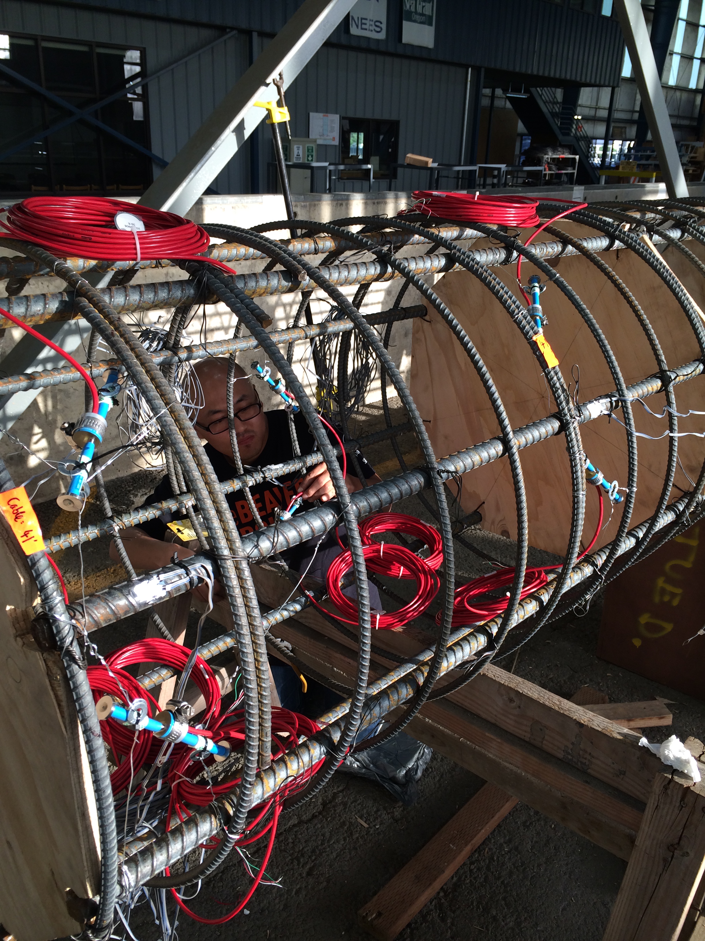
The steel reinforcing cages were constructed in the O.H. Hinsdale Laboratory on the OSU Campus, and fitted with resistance and vibrating wire strain gages to monitor longitudinal and shear strains within the reinforced concrete comprising the test shafts:
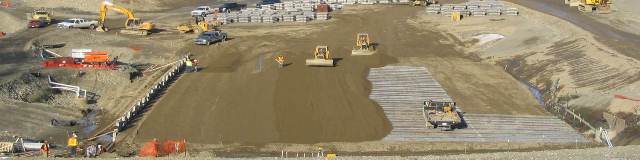
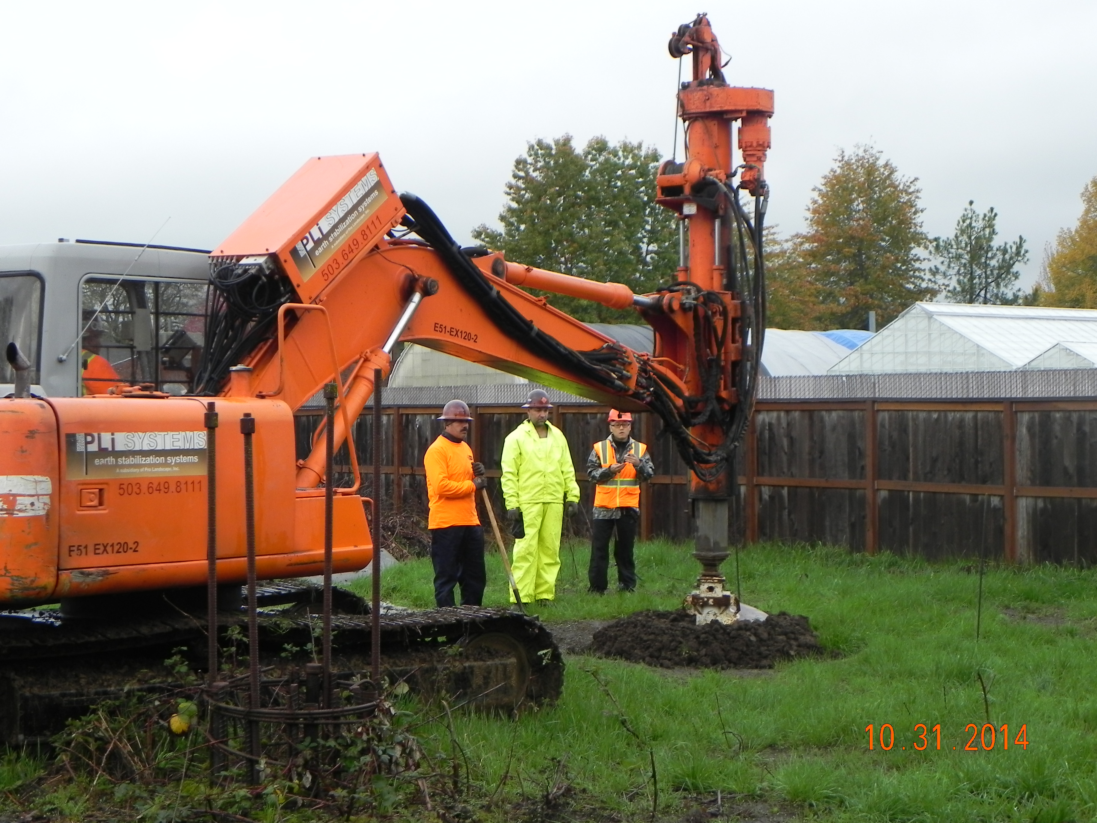
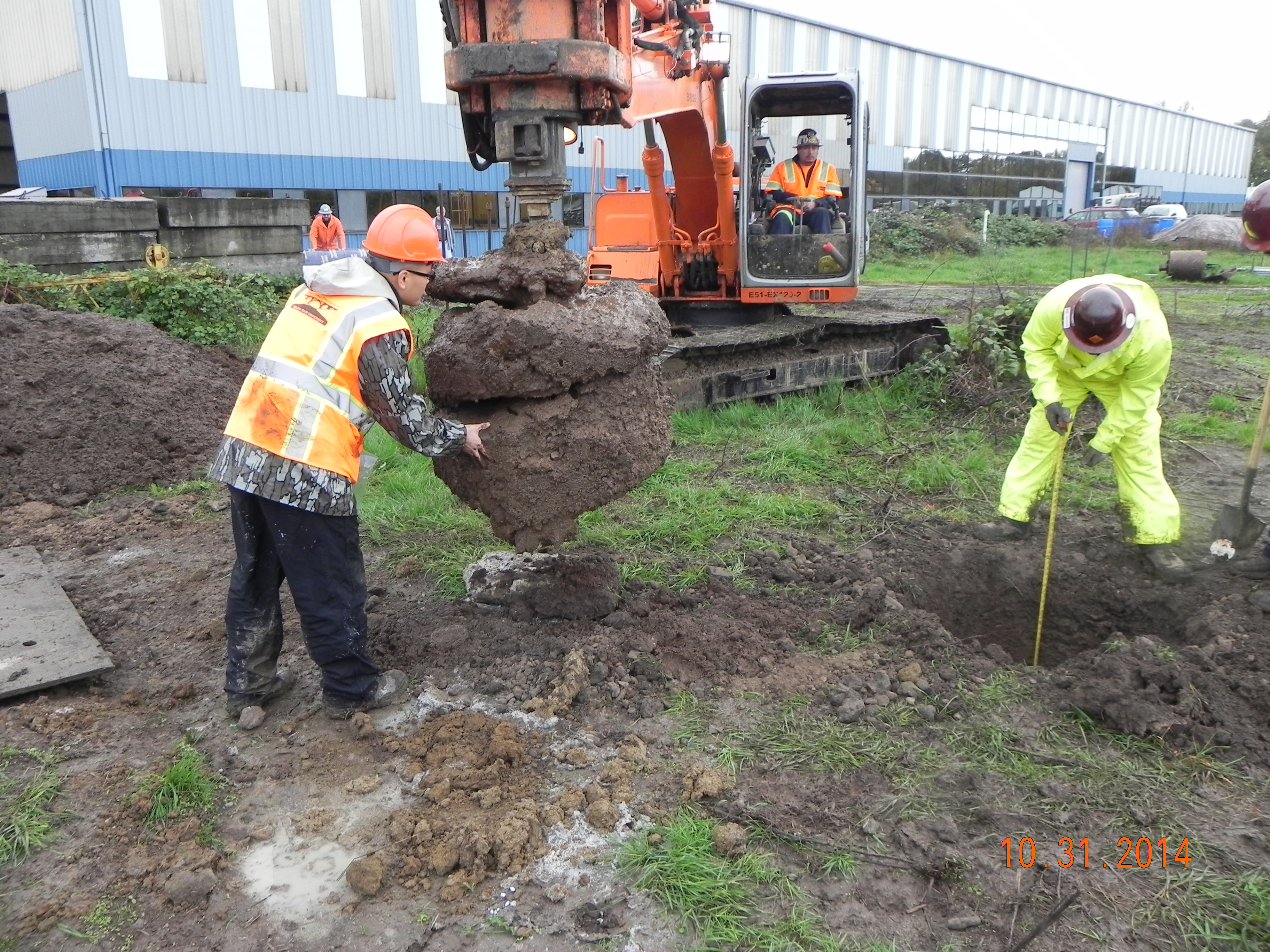
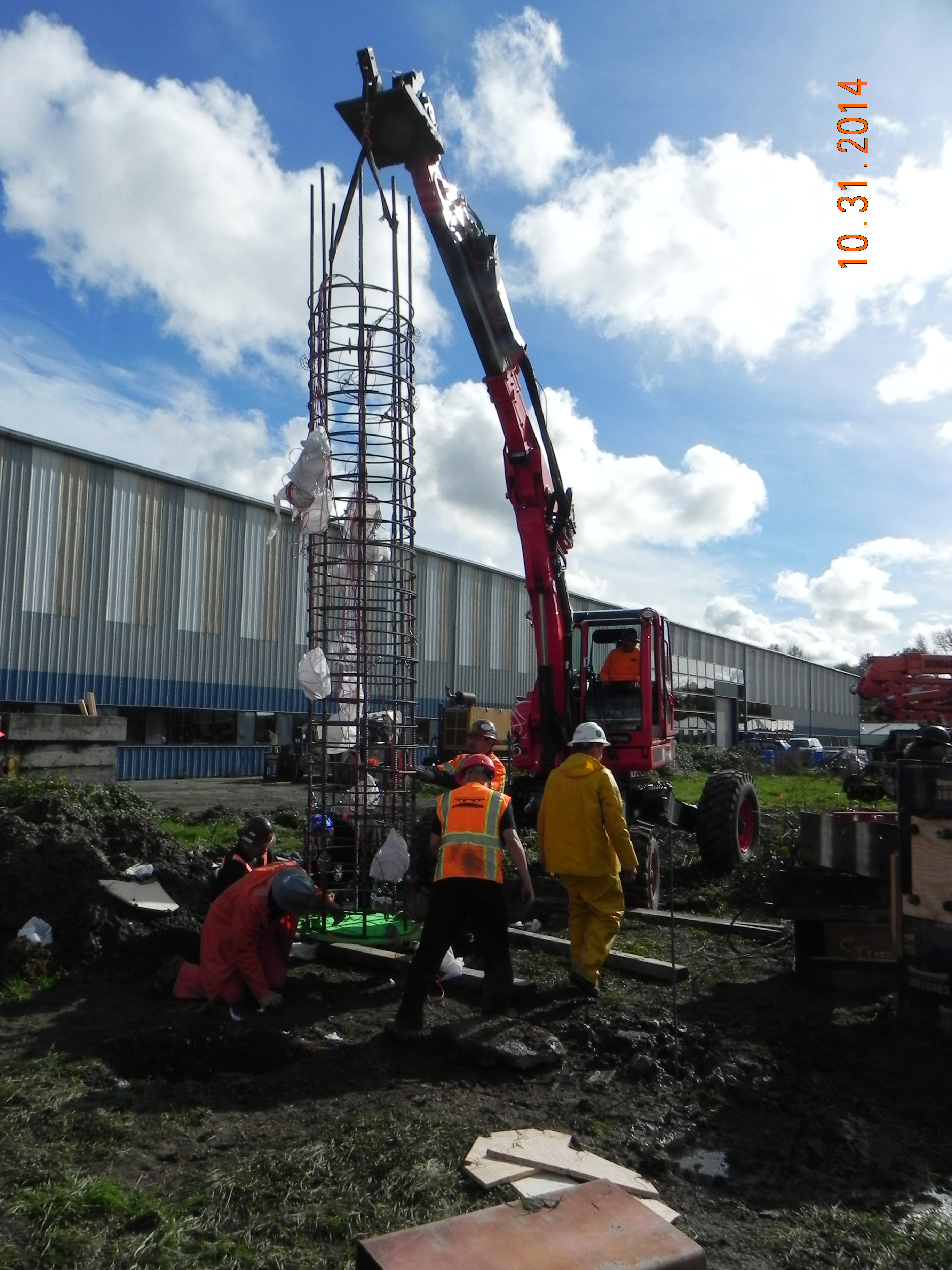
The two test shafts were drilled using a 36" auger and track-mounted Lo-Dril drilling rig. Frequent measurements of the shaft excavation were made to monitor the progress of excavation, which targeted a depth of 4 m (13 ft.). Grab samples of soil from the augers were collected for visual/manual classification and index tests.
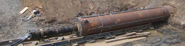
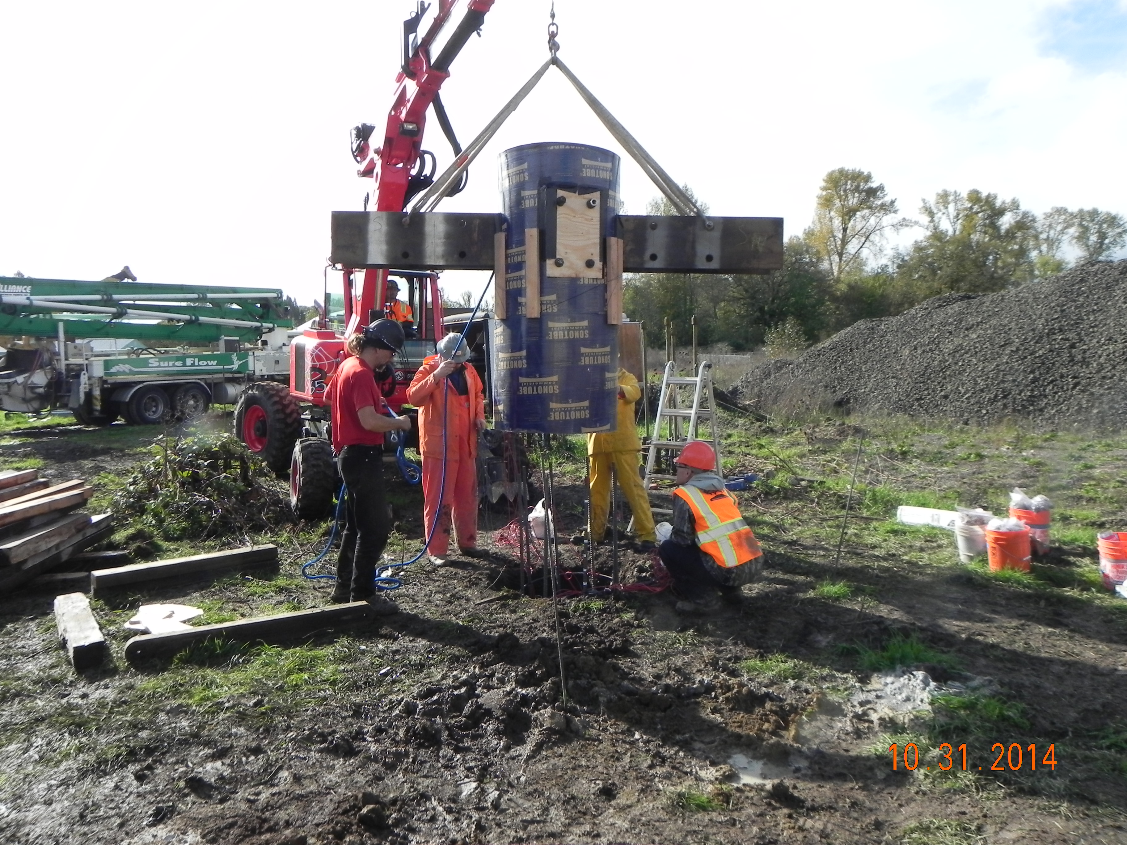
Following excavation of the test shafts, the instrumented reinforcement cages were placed and the H-Pile reinforced sonotube form lowered into place to allow conreting of the above-ground portion of the test specimens.
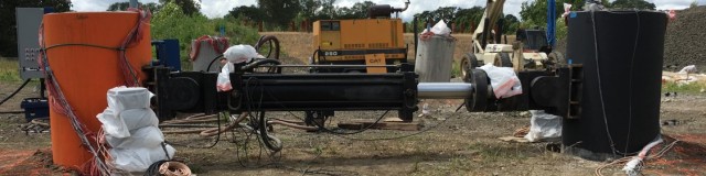
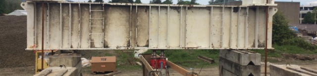
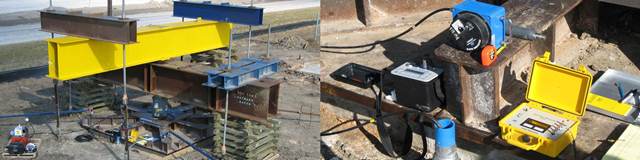
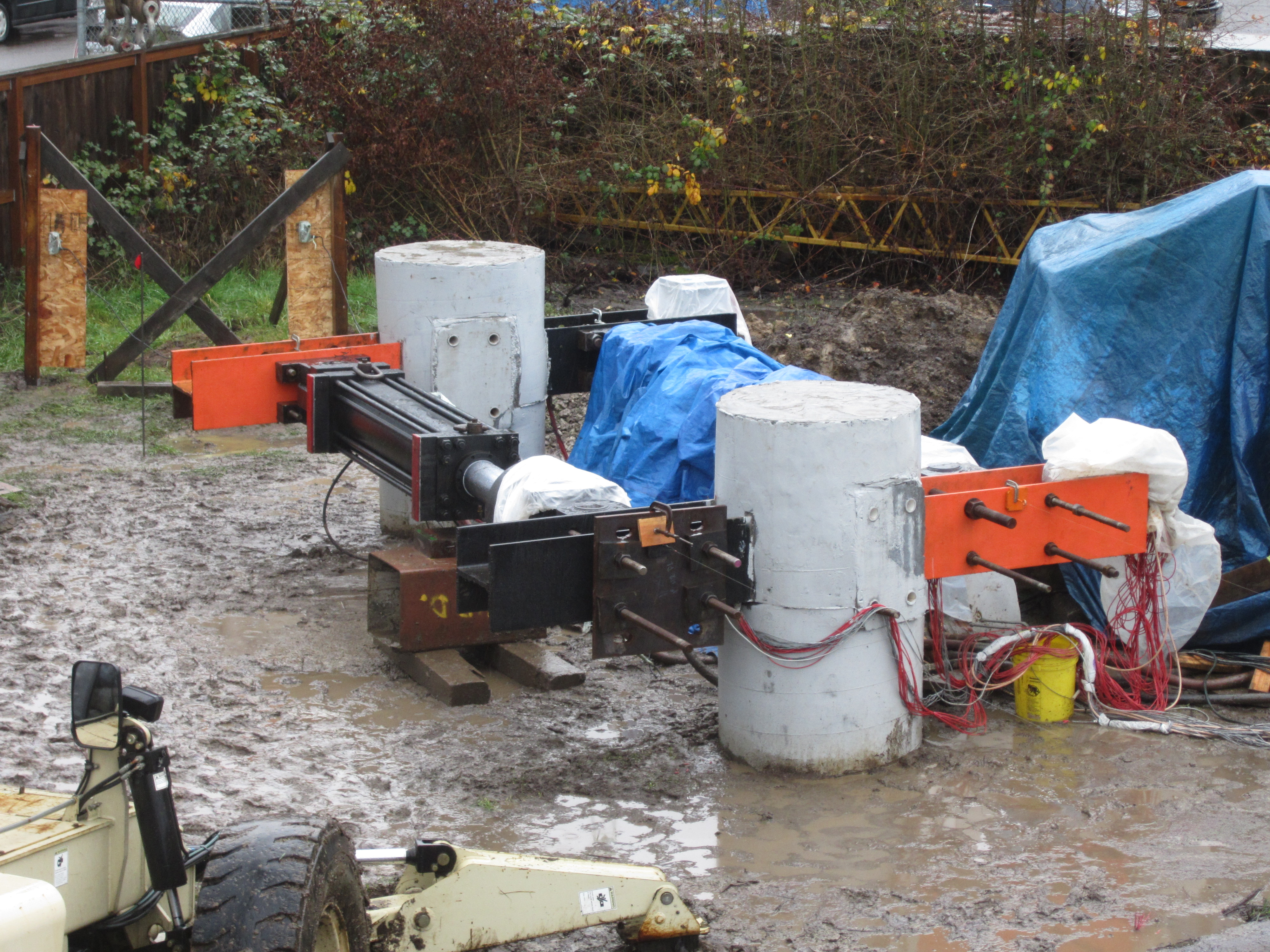
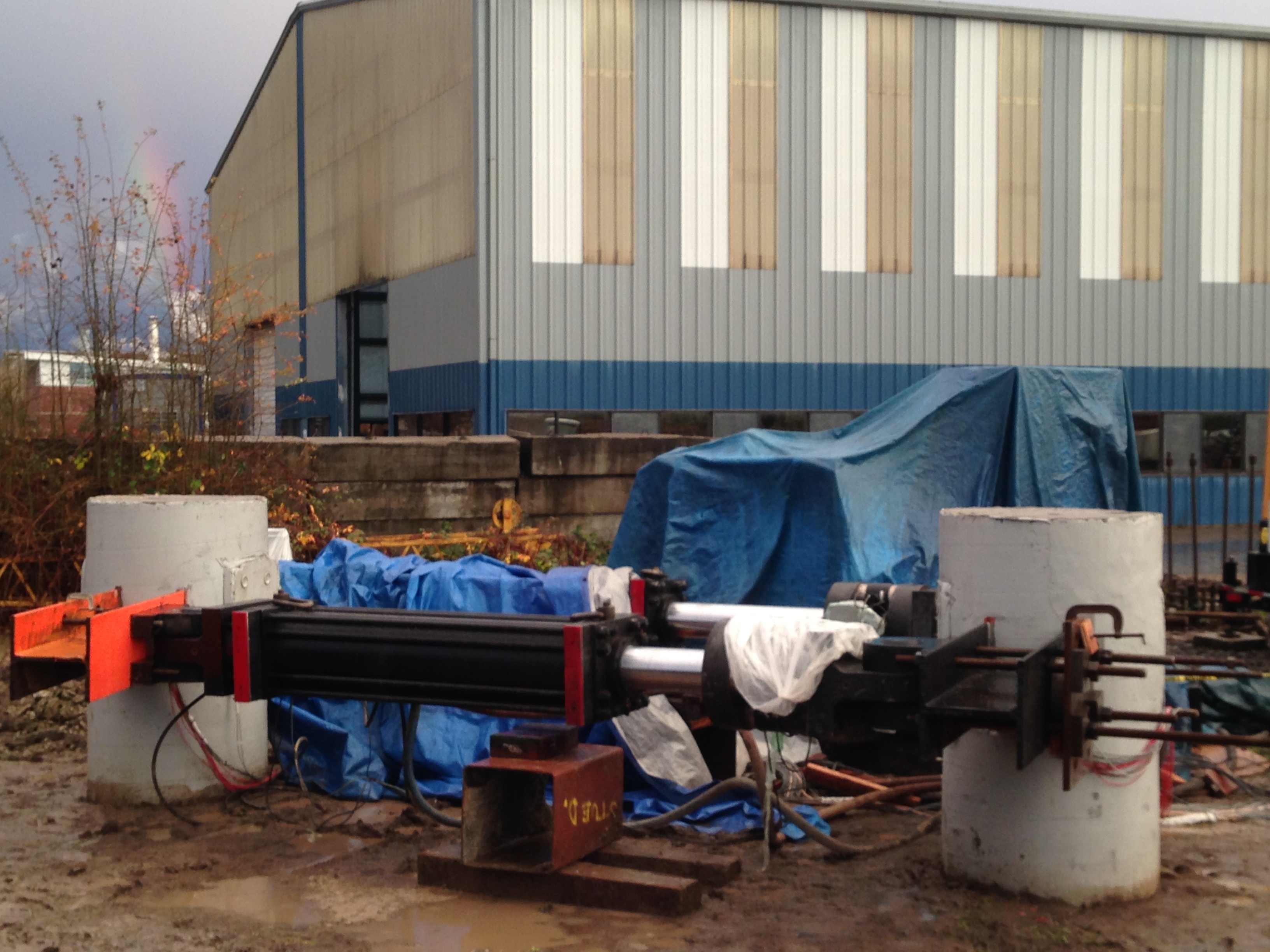
The torsion tests were performed on 15 December, 2014 during a heavy rain storm - perfect conditions! The target magnitudes of torsion were applied by setting one actuator to displace outward and one inward in equal increments - known as a displacement couple. Approximately 50 instruments allowed recording of strains, displacements, and loads throughout the test.
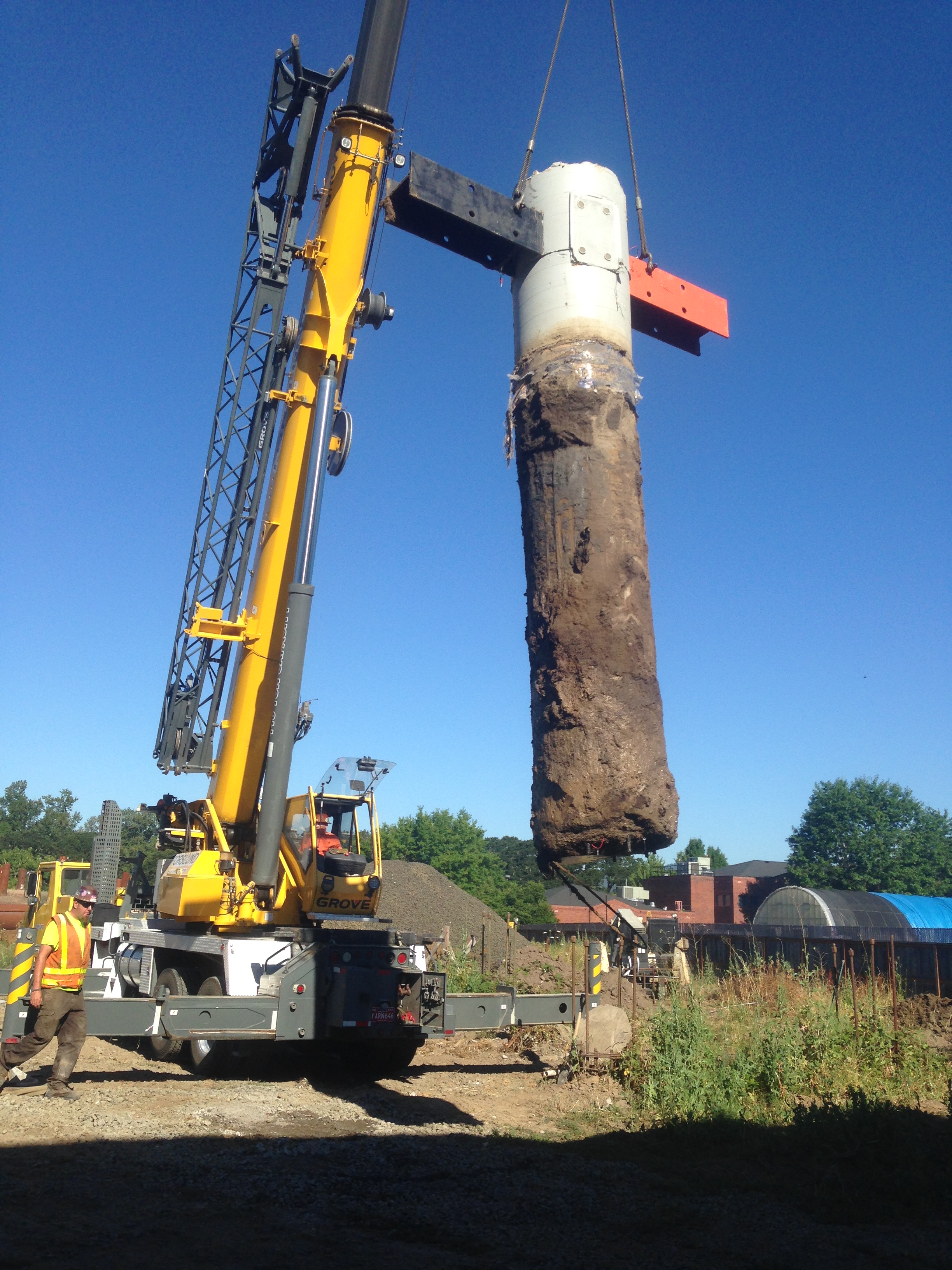
Following the test, the shafts were exhumed, and as-built dimensions measured to improve the accuracy of the back-calculated load transfer. We thank our sponsors (ODOT, PLI Systems, Inc.) for the opportunity to perform this research.