
Ocean Going Robots Accelerometer System
Purpose
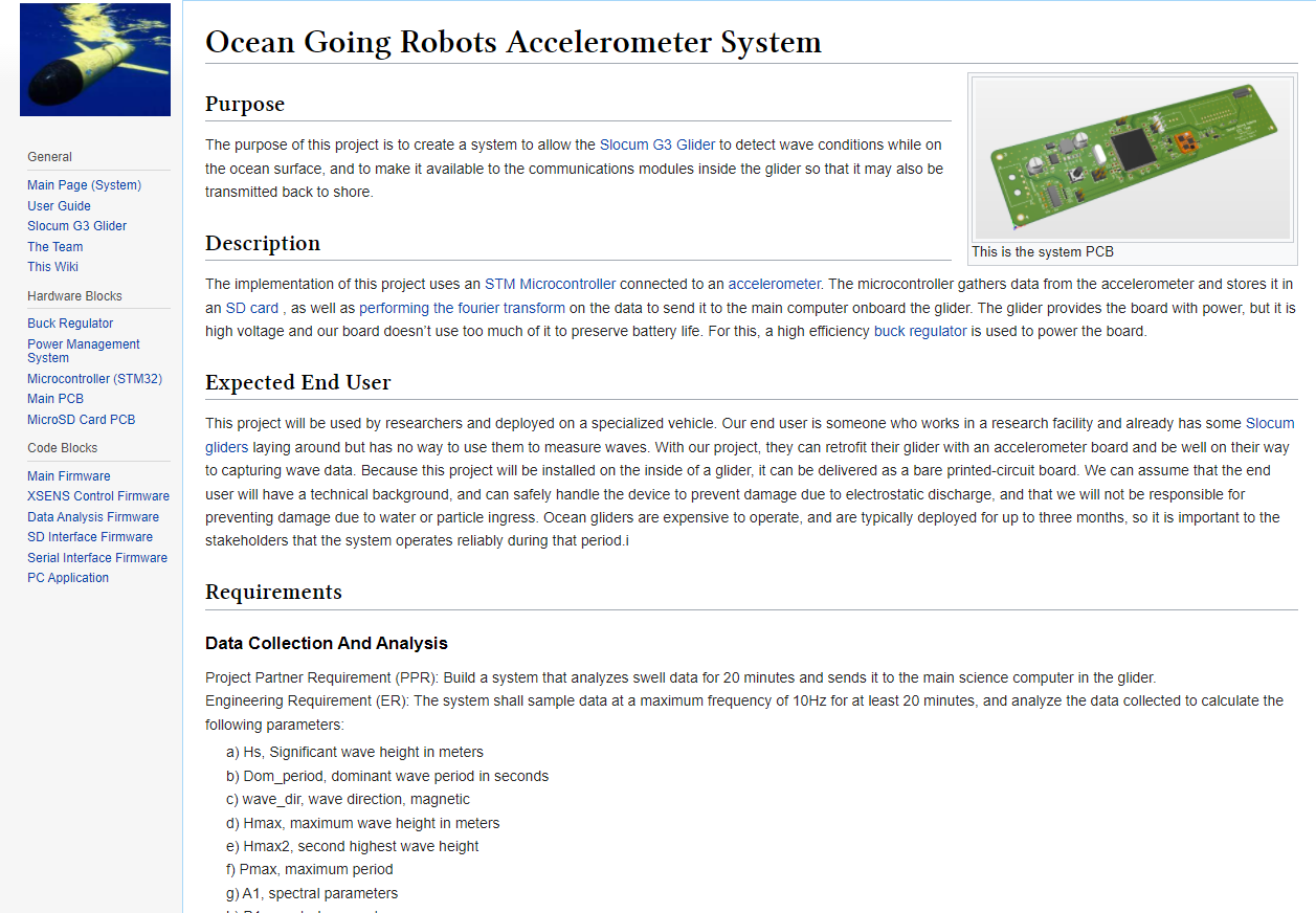
The purpose of this project is to create a system to allow the Slocum G3 Glider to detect wave conditions while on the ocean surface, and to make it available to the communications modules inside the glider so that it may also be transmitted back to shore.
Description
The implementation of this project uses an STM Microcontroller connected to an accelerometer. The microcontroller gathers data from the accelerometer and stores it in an SD card , as well as performing the Fourier transform on the data to send it to the main computer onboard the glider. The glider provides the board with power. The input voltage from the glider is higher, 10-17 Volts, than this project's board needs, 3.3 Volts. A high efficiency buck regulator is used to power the board.
Expected End User
This project will be used by researchers and deployed on a specialized vehicle. Our end user is someone who works in a research facility and already has some Slocum gliders laying around but has no way to use them to measure waves. With our project, they can retrofit their glider with an accelerometer board and be well on their way to capturing wave data. Because this project will be installed on the inside of a glider, it can be delivered as a bare printed-circuit board. We can assume that the end user will have a technical background, and can safely handle the device to prevent damage due to electrostatic discharge, and that we will not be responsible at fileName, float data[], int noElements) for preventing damage due to water or particle ingress. Ocean gliders are expensive to operate, and are typically deployed for up to three months, so it is important to the stakeholders that the system operates reliably during that period.
Requirements
Data Collection And Analysis
- Project Partner Requirement (PPR): Build a system that analyzes swell data for 20 minutes and sends it to the main science computer in the glider.
- Engineering Requirement (ER): The system shall sample data at a maximum frequency
of 10Hz for up to 20 minutes, and analyze the data collected to calculate the
following parameters:
- 1) Hs, Significant wave height in meters
- 2) Dom_period, dominant wave period in seconds
- 3) wave_dir, wave direction, magnetic
- 4) Hmax, maximum wave height in meters
- 5) Hmax2, second highest wave height
- 6) Pmax, maximum period
- 7) ([AB]|[12]) directional wave spectra parameter
- 8) Wave component number
PCB Size
- PPR: Board must fit inside the science bay of the glider
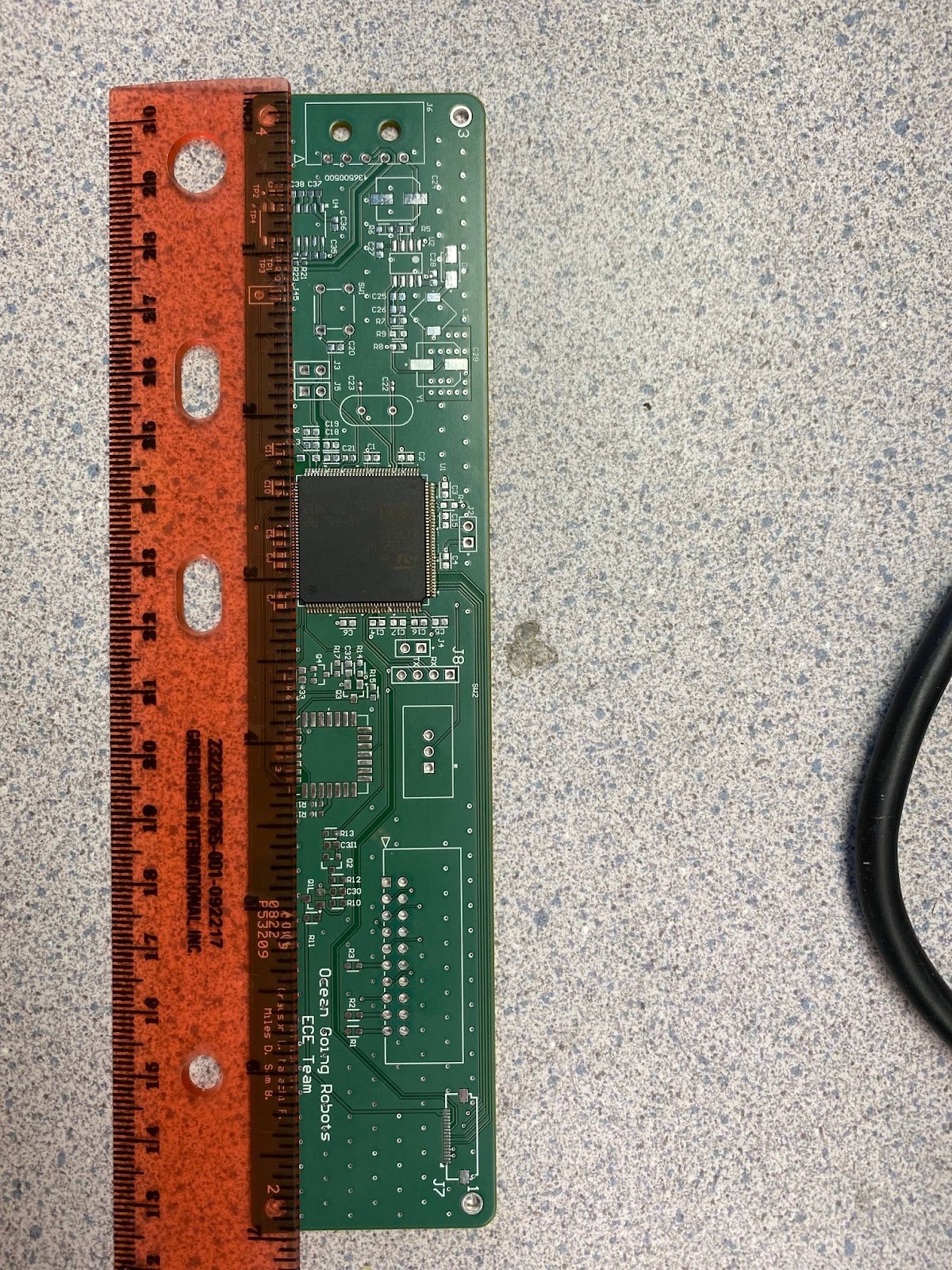
- ER: The microcontroller PCB must be smaller than 7 inches by 1.5 inches (and 2 inches tall) to fit onto the back of the acoustic modem board in the science bay of the glider.
Removable Data Storage
- PPR: Collected data must be available in removable memory.
- ER: Data must be stored to a microSD Card .
Glider Battery Life Impacts
- PPR: Board must not reduce glider's battery life by more than 1%.
- ER: For a 20 minute collection cycle, the system must consume less than 230 Joules.
Data Ease of Access
- PPR: Removable memory must be easily accessible.
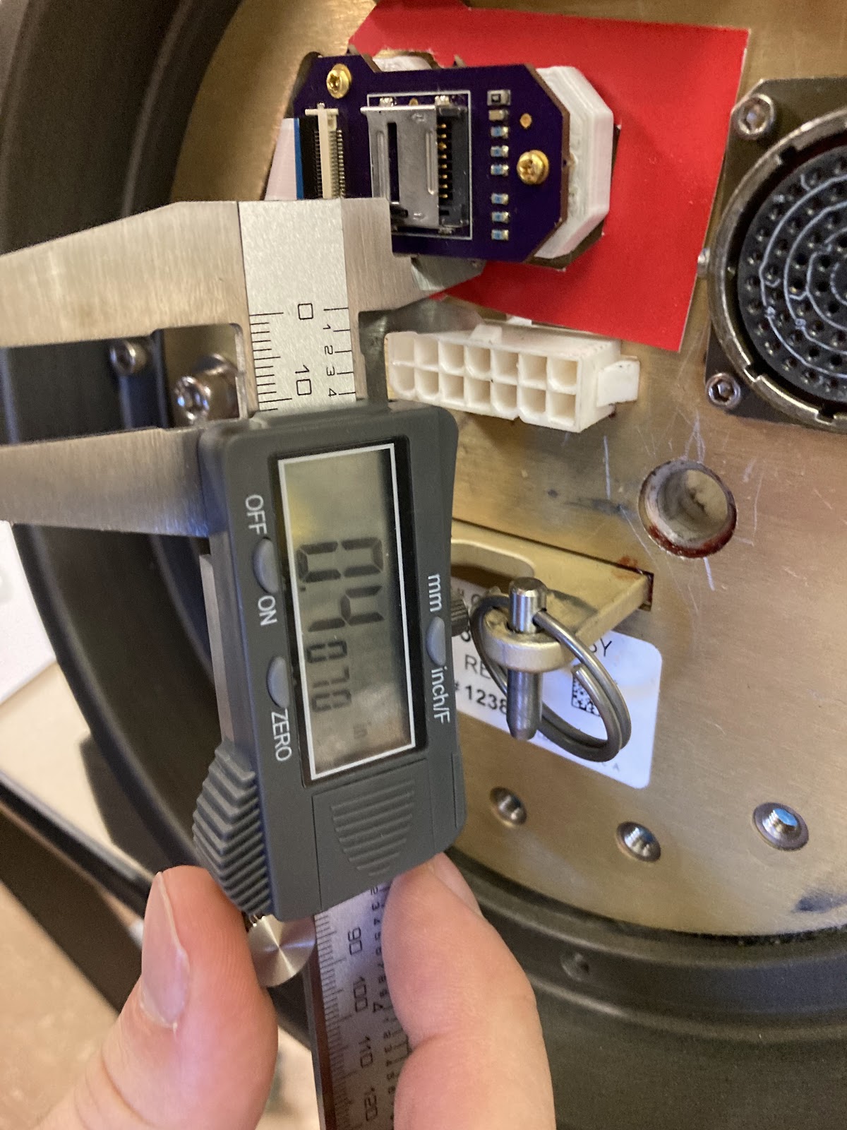
- ER: SD Card and associated PCB will have at least 0.5 inch clearance from nearby connectors.
Project Overview Wiki Page
- PPR: The project must be thoroughly documented.
- ER: A Wiki Page that encompasses all aspects of the project shall be created. Including all design artifacts as well as a user guide .
System Longevity
- PPR: There should be no hardware or firmware bugs that cause the system to stop logging data while in use.
- ER: System must work properly for at least 90 days of continual use.
System Security
- PPR: System must be rugged to withstand the forces associated with being put into and taken out of the ocean.
- ER: System must be able to withstand a drop of at least 10 feet in a test enclosure (sealed PVC pipe) to simulate the payload bay of the glider. The HW and FW must continue to work and the microSD card must stay in the holder and be accessible by FW.
Constraints
- The system may not include a breadboard.
- The final system must contain both of the following: a student designed PCB and a custom Android/PC/Cloud application.
- If an enclosure is present, the contents must be ruggedly enclosed/mounted as evaluated by the course instructor.
- If present, all wire connections to PCBs and going through and enclosure (entering or leaving) must use connectors.
- All power supplies in the system must be at least 65% efficient.
- The system may be no more than 50% built from purchased modules.
List of Blocks
The subsystems that make up the entire system are:
This hardware will be constructed on:
Additionally, the following code blocks will be running on this system:
- Main Firmware
- XSENS Control Firmware
- Data Analysis Firmware
- SD Interface Firmware
- Serial Interface Firmware
As well as the following externally run program:
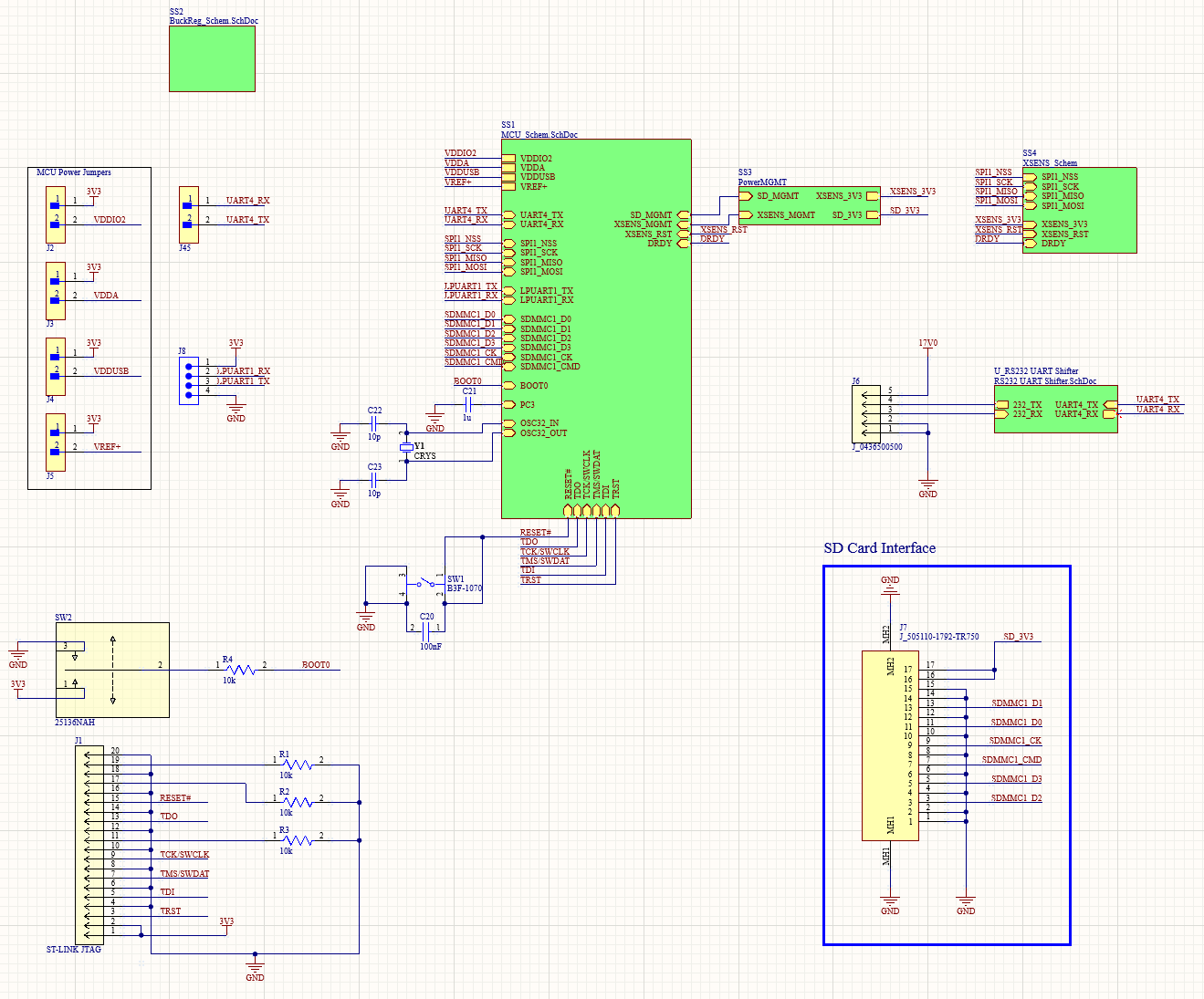
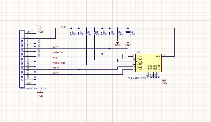
Schematic
PCB
Design Files
Ocean Going Robots Accelerometer System
Purpose
The purpose of this project is to create a system to allow the Slocum G3 Glider to detect wave conditions while on the ocean surface, and to make it available to the communications modules inside the glider so that it may also be transmitted back to shore.
Description
The implementation of this project uses an STM Microcontroller connected to an accelerometer. The microcontroller gathers data from the accelerometer and stores it in an SD card , as well as performing the Fourier transform on the data to send it to the main computer onboard the glider. The glider provides the board with power. The input voltage from the glider is higher, 10-17 Volts, than this project's board needs, 3.3 Volts. A high efficiency buck regulator is used to power the board.
Expected End User
This project will be used by researchers and deployed on a specialized vehicle. Our end user is someone who works in a research facility and already has some Slocum gliders laying around but has no way to use them to measure waves. With our project, they can retrofit their glider with an accelerometer board and be well on their way to capturing wave data. Because this project will be installed on the inside of a glider, it can be delivered as a bare printed-circuit board. We can assume that the end user will have a technical background, and can safely handle the device to prevent damage due to electrostatic discharge, and that we will not be responsible at fileName, float data[], int noElements) for preventing damage due to water or particle ingress. Ocean gliders are expensive to operate, and are typically deployed for up to three months, so it is important to the stakeholders that the system operates reliably during that period.
Requirements
Data Collection And Analysis
- Project Partner Requirement (PPR): Build a system that analyzes swell data for 20 minutes and sends it to the main science computer in the glider.
- Engineering Requirement (ER): The system shall sample data at a maximum frequency
of 10Hz for up to 20 minutes, and analyze the data collected to calculate the
following parameters:
- 1) Hs, Significant wave height in meters
- 2) Dom_period, dominant wave period in seconds
- 3) wave_dir, wave direction, magnetic
- 4) Hmax, maximum wave height in meters
- 5) Hmax2, second highest wave height
- 6) Pmax, maximum period
- 7) ([AB]|[12]) directional wave spectra parameter
- 8) Wave component number
PCB Size
- PPR: Board must fit inside the science bay of the glider
- ER: The microcontroller PCB must be smaller than 7 inches by 1.5 inches (and 2 inches tall) to fit onto the back of the acoustic modem board in the science bay of the glider.
Removable Data Storage
- PPR: Collected data must be available in removable memory.
- ER: Data must be stored to a microSD Card .
Glider Battery Life Impacts
- PPR: Board must not reduce glider's battery life by more than 1%.
- ER: For a 20 minute collection cycle, the system must consume less than 230 Joules.
Data Ease of Access
- PPR: Removable memory must be easily accessible.
- ER: SD Card and associated PCB will have at least 0.5 inch clearance from nearby connectors.
Project Overview Wiki Page
- PPR: The project must be thoroughly documented.
- ER: A Wiki Page that encompasses all aspects of the project shall be created. Including all design artifacts as well as a user guide .
System Longevity
- PPR: There should be no hardware or firmware bugs that cause the system to stop logging data while in use.
- ER: System must work properly for at least 90 days of continual use.
System Security
- PPR: System must be rugged to withstand the forces associated with being put into and taken out of the ocean.
- ER: System must be able to withstand a drop of at least 10 feet in a test enclosure (sealed PVC pipe) to simulate the payload bay of the glider. The HW and FW must continue to work and the microSD card must stay in the holder and be accessible by FW.
Constraints
- The system may not include a breadboard.
- The final system must contain both of the following: a student designed PCB and a custom Android/PC/Cloud application.
- If an enclosure is present, the contents must be ruggedly enclosed/mounted as evaluated by the course instructor.
- If present, all wire connections to PCBs and going through and enclosure (entering or leaving) must use connectors.
- All power supplies in the system must be at least 65% efficient.
- The system may be no more than 50% built from purchased modules.
List of Blocks
The subsystems that make up the entire system are:
This hardware will be constructed on:
Additionally, the following code blocks will be running on this system:
- Main Firmware
- XSENS Control Firmware
- Data Analysis Firmware
- SD Interface Firmware
- Serial Interface Firmware
As well as the following externally run program:
Schematic
PCB
Design Files
User Guide
Installing in the Slocum G3 Glider
Installing our system is simple and easy. You will need a Slocum G3 glider, the MCU main board, the SD card board and clip holder, the SD card board connector cable, a microSD card, and the serial/power connector from the glider to our main board. The installation steps are as follows: Mount the main board onto the back of the modem in the science bay of the glider using screw standoffs and small nuts. Connect the main board to the science computer of the glider using the serial/power cable. Mount the SD card board onto its clip holder. Attach the SD card board to one side of the SD card board connector cable. Attach the other side of the SD card board connector to the connector on the main board. Reassemble the glider such that the SD card board comes out the hole in the bottom near the big round connector with many pins. Use the clip holder to mount the SD card board on the edge of the hole Open the SD card holder on the board and insert the microSD card. Your system is now fully installed and ready to use.
Power
This system employs a 3.3V buck regulator power supply on the main board to provide power to the microcontroller, accelerometer, and SD card. This means that the power input to the system can be a wide range. The system is optimized for a 17V battery but the regulator can take any voltage between 5V and 28V. It is not recommended to push the circuit to its extremes. The power consumption of the device is minimized by cutting power to certain peripherals while they are not in use. Over a 20 minute collection cycle, our system uses only ~190 Joules. In a standard G3 glider running seven 20 minute collection cycles per day, this will use less than 1 percent of the glider's battery life.
Communication Protocols
The main communication to our system is through serial. It is through serial that the system knows to start and stop collecting data. When the system starts receiving power from the glider, it will wait for the serial message from the science computer:
set time %lf\r
Where %lf is a floating point number representing Unix time, UTC seconds since 1970-01-01 00:00:00. After receiving that message and parsing out the UTC timestamp, our system will send an ACK message back to the glider saying:
TIME SET:\r
After this the system will start collecting data and storing it to the SD card indefinitely until the science computer sends the serial message:
restart\r
Upon receiving this message, our system will store the remaining data to the SD card, run a data analysis function on the full data set, then return the following parameters as a CSV over serial:
- heading, heading in degrees magnetic
- hs, significant wave height in meters
- dom_period, wave period in seconds
- wave_dir, wave direction, magnetic
- hmax, maximum wave height in meters
- hmax2, (I think this is the second highest wave, but I'm not 100% sure.)
- pmax, maximum period
- a1, spectral parameters
- b1, spectral parameter
- a2, spectral parameter
- b2, spectral parameter
- index, Wave component number, 1...n where is n is chosen before. 0 indicates this is the last record.
- timestamp, Unix time, UTC seconds since 1970-01-01 00:00:00
When the science computer receives a 0 in the 12th field of this CSV, it will know that this is the final piece of information and it will cut power to the accelerometer system. At this point the glider is ready to dive and our system will be turned off until the glider is ready to collect accelerometer data again. At the end of the glider’s stint flying around the ocean collecting data, you can open up the glider and retrieve the SD card from the SD card board. This SD card will have all of the raw accelerometer data collected in each 20 minute interval. There’s a csv file for each 20 minute interval, named after the UTC timestamp given to the system at the beginning of that interval. Within each csv, there is a header showing the number of items in the file, and then that many lines of data points. Each data point has 11 parameters and are ordered as shown below:
Slocum G3 Glider
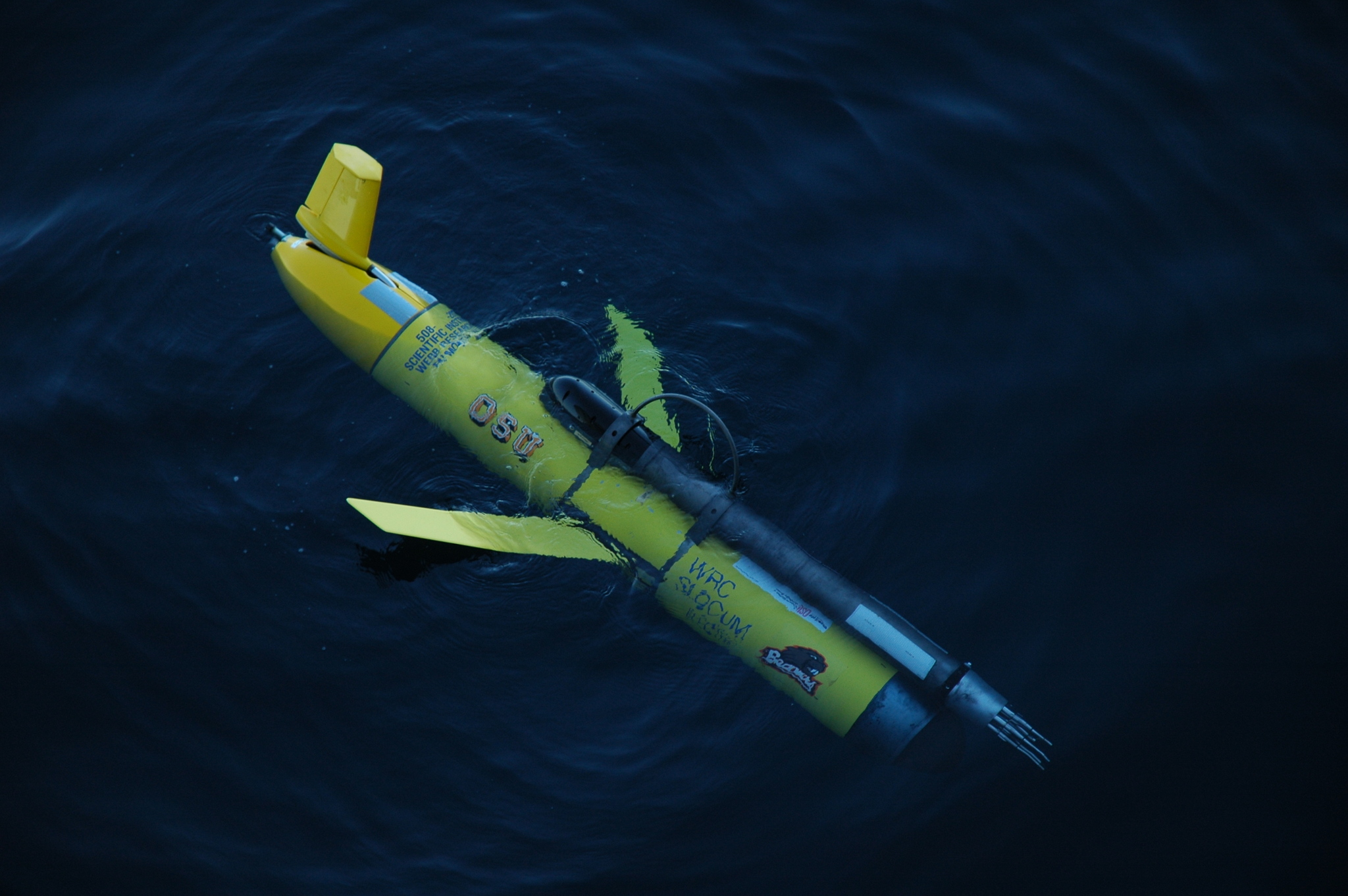
The Slocum Glider is a type of Autonomous Underwater Vehicle (AUV) designed to monitor underwater conditions such as ocean salinity, temperature, depth, etc. It operates by using ballast tanks and short wings on its sides to propel itself through the water. While in operation it dives and resurfaces, and that process causes water to move over its wings, propelling it forwards. After a predetermined number of glide cycles, the glider resurfaces to transmit the collected data back to shore for analysis. The end-user group that this project is focused on is the College of Earth, Ocean, and Atmospheric Sciences here at Oregon State University which uses these gliders around the world for a number of research projects.
The Team

Team Values
We value hard work, creativity, and silliness
Team Members
Miles Drake
Miles worked on the Buck Regulator block and the Power Management block.
Malachi Fisher
Malachi worked on the Micro SD Card PCB block and the SD Interface Firmware block.
Samuel Barton
Sam worked on the Data Analysis Firmware block, the Main PCB block and the Microcontroller block.
Grayson Lewis
Grayson worked on the
Accelerometer and Firmware
blocks, the
PC Application
block, the
Serial Interface Firmware
block and the
Main PCB
block.
This Wiki
About
This wiki includes everything you need to know about our system. There is detailed documentation on every block of the system, as well as a very helpful user guide .
Why?
This wiki was created because we set it as a requirement for our project. It is very important to have well documented work, and what better way to document something than on the internet?
Buck Regulator
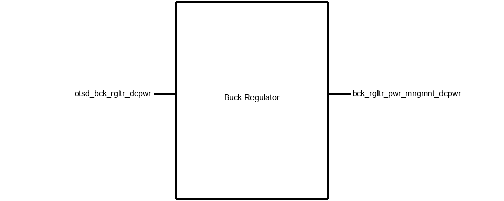
Block Description
This block includes the buck regulator power supply for the main board PCB. The buck regulator block is a necessary part of the system. The Slocum G3 Glider is able to supply between 7 and 17 volts to our board, but the microcontroller that we are using needs a 3.3V supply. We will be designing a buck regulator power supply for our board using the TPS54232DR. Since this is the same chip that is used for the tech demo, we’ll use the tech demo board to prove its functionality before implementing it in the final PCB.
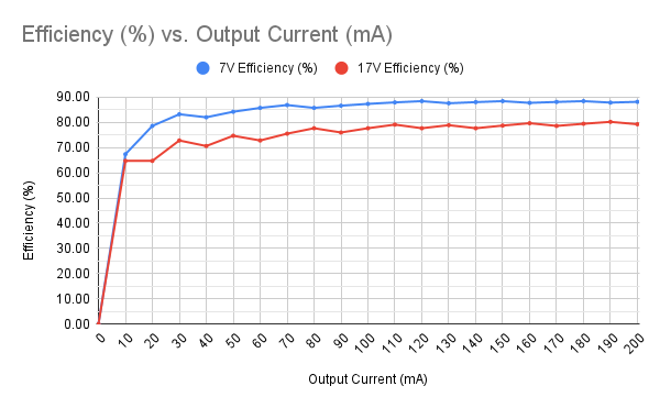
Regulator Efficiency
The following graph shows the experimental efficiency of the buck regulator prototype board over a range
of current draws. The graph shows the efficiency for both a 7V and a 17V input voltage, the lower and upper
range of supply voltage from the glider.
Interfaces
Incoming DC Power
Signal Name: otsd_bck_rgltr_dcpwer
Properties:
- Inominal: 8mA
- Ipeak: 25mA
- Vmax: 17V
- Vmin: 7V
- Vnominal: 17V
Outgoing DC Power
Signal Name: bck_rgltr_pwr_mngmnt_dcpwr
- Inominal: 31mA
- Ipeak: 97mA
- Vmax: 3.35V
- Vmin: 3.1V
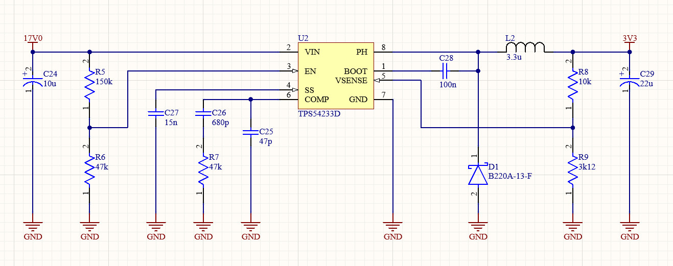
Schematic
Power Management System
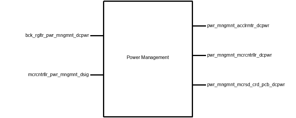
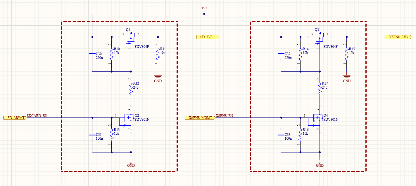
Block Description
This block includes a power management circuit to cut power to the SD card and the accelerometer. Since the SD card uses a considerable amount of power while it is in sleep mode, we would like to be able to cut its power line while it is not being written to or read from. For this we will need a simple MOSFET circuit that uses the output of a GPIO pin on the microcontroller to control the flow of power to the SD card. We will use an identical circuit to cut the power to the accelerometer when we aren’t using it (while performing the Fourier transform). We plan to model the circuit in LTSpice before implementing it in the final PCB.
Interfaces
Incoming DC Power
Signal Name: bck_rgltr_pwr_mngmnt_dcpwr
Properties:
- Inominal: 31mA
- Ipeak: 97mA
- Vmax: 3.35V
- Vmin: 3.1V
DC Power to Accelerometer
Signal Name: pwr_mngmnt_acclrmtr_dcpwr
Properties:
- Inominal: 15mA
- Ipeak: 33mA
- Vmax: 3.4V
- Vmin: 2.9V
DC Power to Microcontroller
Signal Name: pwr_mngmnt_mcrcntrllr_dcpwr
Properties:
- Inominal: 11mA
- Ipeak: 14mA
- Vmax: 3.4V
- Vmin: 1.7V
DC Power to MicroSD Card
Signal Name: pwr_mngmnt_mcrsd_crd_pcb_dcpwr
Properties:
- Inominal: 5mA
- Ipeak: 50mA
- Vmax: 3.4V
- Vmin: 2.9
Power Management Control Signals
Signal Name: mcrcntrllr_pwr_mngmnt_dsig
Properties:
- Logic Level: 3.3V
- Current Draw: 500uA
- Active High
Schematic
Microcontroller (STM32)
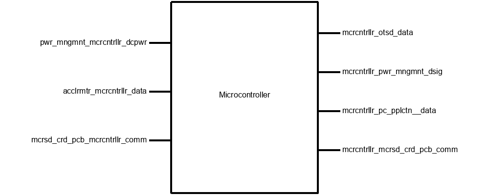
Block Description
The purpose of the Microcontroller block (championed by Samuel Barton) is to run all firmware blocks including data analysis, data transfer, serial communication firmware, etc., as well as receive and transmit data between the Inertial Measurement Unit (IMU), SD Card, and the science computer found inside the payload bay of the glider. This block will be the primary means of processing the measurement data collected by the XSENS MTI-3 IMU. With that in mind, the design for this block will be centered around an STM32 L4R5 series microcontroller that offers 2 Mbytes of Flash memory and 640k RAM memory to ensure ample memory to hold all data in memory before being transmitted over the satellite link to shore.
Interfaces
DC Power to Microcontroller
Signal Name: pwr_mngmnt_mcrcntrllr_dcpwr
Properties:
- Inominal: 11mA
- Ipeak: 14mA
- Vmax: 3.4V
- Vmin: 1.71V
Accellerometer Microcontroller Communications
Signal Name: acclrmtr_mcrcntrllr_data
- Messages: Rotation in Quaternions, 4x 32-bit floating point numbers
- Messages: Cartesian(XYZ) Accelleration, 3x 32-bit floating point numbers (NOTE: This is a unitless measurement normalized to 1)
- Protocol: SPI
Microcontroller External Communications
Signal Name: mcrcntrllr_otsd_data
Properties:
- Datarate: 9600 baud
- Messages: Significant wave height (m), dominant period (s), wave direction (degrees magnetic), maximum wave height (m), maximum period (s), four spectral parameters, a wave component number (if needed), and a timestamp (UTC).
- Protocol: RS232 to science computer using level shifters
Microcontroller Signals to Power Management
Signal Name: mcrcntrllr_pwr_mngmnt_dsig
Properties:
- Logic Level: 3.3V
- Current Draw: 500uA
- Active High
Microcontroller PC Application Communications
Signal Name: mcrcntrllr_pc_pplctn_data
Properties:
- Datarate 115200 Baud
- Messages: Roll, Pitch Yaw, orientation in quaternions
- Cartesian (XYZ) Accelleration
- Protocol: UART
Microcontroller MicroSD Card Communications
Signal Name: mcrcntrllr_mcrsd_crd_pcb_comm, mcrsd_crd_pcb_mcrcntrllr_comm
Properties:
- Protocol: SD Protocol
- Vmax: 3.4V
- Vmin: 3.3V
Schematic
_schem.png)
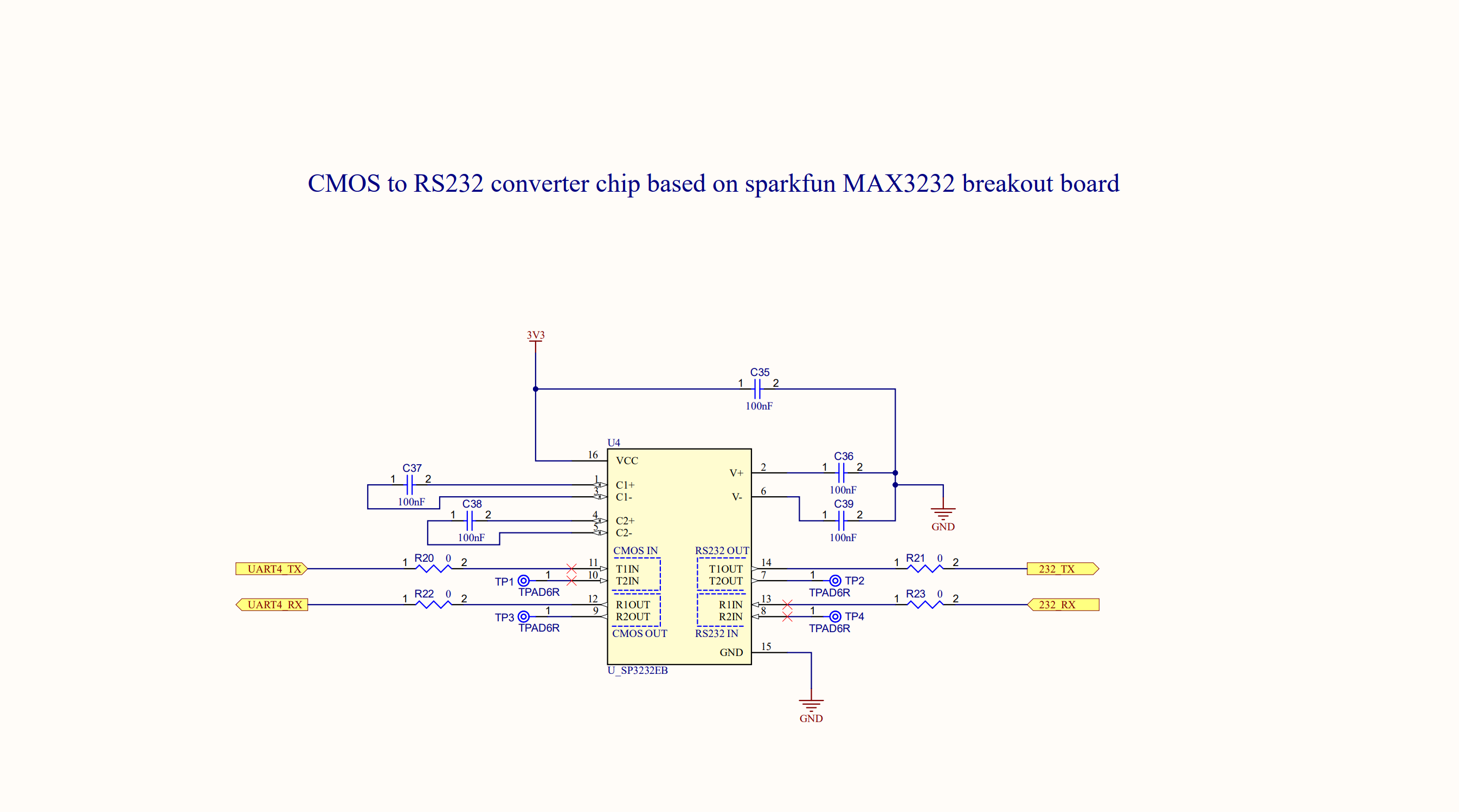
RS232 Level Converter
Block Description
This block is a level converter to convert the communication signal levels between this board and the glider. The glider requires signals between 0 and 12V, and our board uses 3.3V communications. This converter circuit is based around the SP3232EB level converter chip.
Schematic
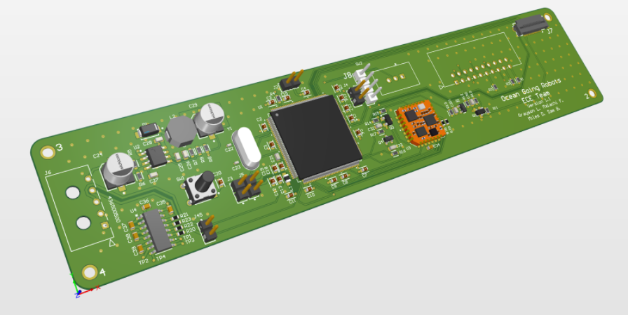
Main PCB

Block Description
This block encompasses the main PCB we will mount the system onto. This will then be mounted onto the back of the acoustic modem PCB support plate in the science bay of the glider . This block is necessary because without it the system would not be secure in the glider and would not be able to be mounted properly. The PCB will also have connectors that will be used to supply the system with power, to communicate with the science computer onboard the glider, and send data out to the external SD Card.
Interfaces
Main Board Mechanical Connections
Signal Name: otsd_mn_brd_pcb_mech
Properties:
- Fasteners: Mounting screws to attatch PCB to the metal plates in the payload of the glider
- Fasteners: Four screws on the four corners of the PCB
- Pulling Force: The PCB must stay connected in the payload bay under a dropping force of 5G's.
PCB
For a full schematic and layout, check out this pdf. For oohs and ahhs, look no further...
MicroSD Card PCB
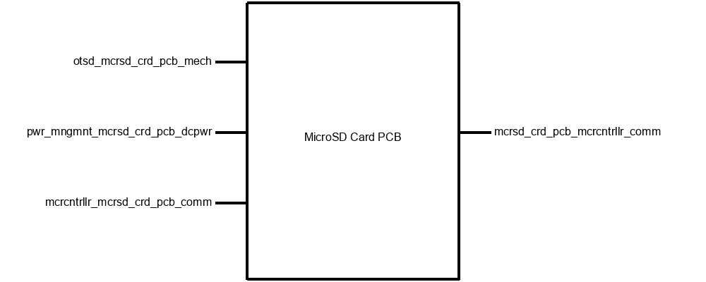
Block Description
This block is the PCB that the SD card will be mounted to. Without it, the SD card will not be able to be properly secured to the inside of the glider. It will need to be small enough to fit between the connectors on the wall of the glider bay without compromising the ability to remove the connectors from their sockets.
Interfaces
MicroSD Board Mechanical Connections
Signal Name: otsd_mcrsd_pcb_mech
Properties:
- Fasteners: SD Card Socket
- Fasteners: Minimum 8 pin ribbon cable connector
- Fasteners: Mounting Hardware, metal screws with standoff
Power Management to MicroSD Card PCB DC Power
Signal Name: otsd_mn_brd_pcb_mech
Properties:
- Inominal: 5mA
- Ipeak: 50mA
- Vmax: 3.4
- Vmin: 3.4
Microcontroller MicroSD Card Communications
Signal Name: mcrcntrllr_mcrsd_crd_pcb_comm, mcrsd_crd_pcb_mcrcntrllr_comm
Properties:
- Protocol: SD Protocol
- Vmax: 3.4V
- Vnominal: 3.3V
Schematic
XSENS Control Firmware
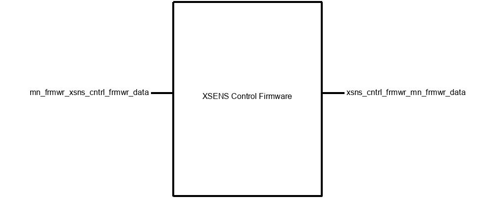
Block Description
This block encompasses the code that will be on the STM32 microcontroller used to interface with the XSENS Accelerometer chip. It will handle the initial handshake between the accelerometer and the microcontroller, and handle the transfer of commands from the microcontroller to the accelerometer as well as the transfer of data from the accelerometer to the microcontroller. This block is necessary because without it we would be unable to retrieve the data from our accelerometer.
Interfaces
Main Firmware to XSENS Control Firmware
Signal Name: mn_frmwr_xsns_cntrl_frmwr_data
Properties:
- Messages: Get Measurements
- Messages: Reset XSENS
- Messages: Configure XSENS
XSENS Control Firmware to Main Firmware
Signal Name: xsns_cntrl_frmwr_mn_frmwr_data
Properties:
- Messages: Cartesian Magnetometer Measurement: 3x 32-bit floating point numbers
- Messages: Rotation in Quartenions: 4x 32-bit floating point number
- Messages: Cartesian (XYZ) Acceleration: 3x 32-bit floating point numbers
Function Definitions
#include/* void power_on_xsens(); * * desc: * * inputs: none * * returns: void * */ /* void power_off_xsens(); * * desc: formats the SD card to FAT file system * * inputs: none * * returns: void * */ /* void flush_buf_xsens(uint8_t* buf, int len); * * desc: Flushes the XSENS buffer, fills a passed array with zeros * * inputs: uint8_t* buf : array of chars to be flushed * int len : length of array to be flushed * * returns: void * */ /* int cfg_protocol_xsens(uint8_t* version, uint8_t* data_cfg_test) * * desc: Configure protocol, should be called before reset_xsens() * * inputs: uint8_t* version : function will fill this pointer with version * uint*_t* data_cfg_test : function will fill this pointer with data * * returns: int * 0: Operation Failed * 1: Operation Successful * */ /* int data_ready_xsens(int timeout); * * desc: Wait for data ready pin to go high with a configurable timeout; * * inputs: int timeout : Number of milliseconds before timeout * * returns: int * 0: Operation Failed * 1: Operation Successful * */ */ int reset_xsens(); * * desc: Reset the xsens, called after cfg_protocol_xsens() * * inputs: none * * returns: int * 0: Operation Failed * 1: Operation Successful * */ */ int goto_config_xsens(); * * desc: put the xsens in configuration mode * * inputs: none * * returns: int * 0: Operation Failed * 1: Operation Successful * */ /* int config_xsens(); * * desc: Configure output mode of xsens. the xsens MUST be in configuration mode for this to work!! * * inputs: none * * returns: int * 0: Operation Failed * 1: Operation Successful * */ /* int goto_measurement_xsens(); * * desc: Puts the XSENS into measurement state * * inputs: none * * returns: int * 0: Operation Failed * 1: Operation Successful * */ /* uint32_t bytes_2_int(uint8_t* pointer); * * desc: Concatenates an array of 4 bytes into one 4 byte int * * inputs: unint_t* pointer: array of 4 bytes to be concatenated into one 4 byte int * * returns: 4 byte int * */ /* float bytes_2_float(uint8_t* pointer); * * desc: Concatenates an array of 4 bytes into one 4 byte float * * inputs: uint_t* pointer: an array of 4 bytes to be concatenated into one 4 byte float * * returns: float * */ /* void read_pipe_status_xsens(uint16_t* notificationMessageSize, uint16_t* measurementMessageSize); * * desc: Reads notification message size and measurement message size into pointers * * inputs: uint16_t* notificationMessageSize : pointer where the notification message size will be stored after being read from XSENS * uint16_t* measurementMessageSize : pointer where the measurement message sizw will be stored after being read from XSENS * * returns: void * */ /* void get_packet_xsens(uint8_t* rx_buf, float* timestamp, float* q1, float* q2, float* q3, float* q4, float* ax, float* ay, float* az, float* mx, float* my, float* mz); * * desc: Gets data packet from XSENS * * inputs: uint8_t* rx_buf : raw data from XSENS, will be parsed into the following pointers * float* timestamp : pointer to store timestamp read from XSENS * float* q1 : pointer to store quaternion 1 data read from XSENS * float* q2 : pointer to store quaternion 2 data read from XSENS * float* q3 : pointer to store quaternion 3 data read from XSENS * float* q4 : pointer to store quaternion 4 data read from XSENS * float* ax : pointer to store x accelleration data read from XSENS * float* ay : pointer to store y accelleration data read from XSENS * float* az : pointer to store z accelleration data read from XSENS * float* mx : pointer to store x magnetic heading data read from XSENS * float* my : pointer to store y magnetic heading data read from XSENS * float* mz : pointer to store z magnetic heading data read from XSENS * * returns: void * */ /* void get_raw_from_pipe_xsens(uint8_t pipe, uint8_t* bytearray, int len); * * desc: gets messages from the XSENS (status message, etc) * * inputs: uint8_t pipe : Selects whether to read from the 0x06 pipe or the notification pipe. 0x05 for notification, 0x06 for measurment. * uint8_t* bytearray : array of bytes to read data into * int len : length of byte array * * returns: void * */
Main Firmware
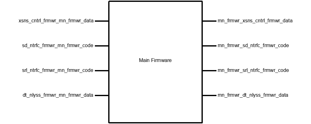
Block Description
This block includes the code that will run on the STM32 microcontroller to perform the memory management functions. This block is necessary because there are memory management tasks that do not fit into one of the other firmware blocks.
Interfaces
Main Firmware XSENS Control Data
Signal Name: mn_frmwr_xsns_cntrl_frmwr_data
Properties:
- Messages: Get Measurements
- Messages: Reset XSENS
- Messages: Configure XSENS
Main Firmware to SD Interface to MicroSD Firmware Code
Signal Name: mn_frmwr_sd_ntrfc_frmwr_code
Properties:
- Data: Populated array of floats
- Data: Populated Int Pointer
- Data: Null Int Pointer
- Data: Timestamp (Filename)
- Data: Null float array pointer
Main Firmware Serial Interface Firware Code
Signal Name: mn_frmwr_srl_ntrfc_frmwr_code
Properties:
- Data: Numbers and strings to be transmitted via a UART Module
- UART Selection: Which UART interface should be used to transmit/receive
- Baud Rate: Speed the UART should operate at.
Main Firmware Data Analysis Data
Signal Name: mn_frmwr_dt_nlyss_frmwr_data
Properties:
- Messages: Acceleration Data in N-Direction (32-bit floats): Acceleration North-South
- Messages: Acceleration Data in U-Direction (32-bit floats): Vertical acceleration data
- Messages: Acceleration Data in E-Direction (32-bit floats): Acceleration East-West
XSENS Control Firmware Main Firmware Data
Signal Name: xsns_cntrl_frmwr_mn_frmwr_data
Properties:
- Messages: Cartesian Magnetometer Measurement: 3x 32-bit floating point numbers
- Messages: Rotation in Quaternions: 4x 32-bit floating point numbers
- Messages: Cartesian (XYZ) Acceleration: 3x 32-bit floating point numbers
SD Interface Firmware Main Firmware Code
Signal Name: sd_ntrfc_frmwr_mn_frmwr_code
Properties:
- Return Value: Error Code
- Data: Populated array of floats from file on uSD
- Return Value: Number of floats Read
Serial Interface Firmware Main Firmware Code
Signal Name: srl_ntrfc_frmwr_mn_frmwr_code
Properties:
- Data Identifier: The type of data that is being received
- Status: Errors, and/or whether there is data in the receive buffers of the UARTs
- Data: Numbers and strings received from UART modules
Data Analysis Main Firmware Data
Signal Name: dt_nlyss_frmwr_mn_frmwr_data
Properties:
- Messages: Dominant Period in E Direction (s)
- Messages: Dominant Period in U Direction (s)
- Messages: FFT Results in Upward (U) Direction (Real and Complex Values)
- Messages: FFT Results in Northward (N) Direction (Real and Complex Values)
- Messages: FFT Results in Eastward (E) Direction (Real and Complex Values)
- Messages: Dominant Period in N Direction (s)
Data Analysis Firmware
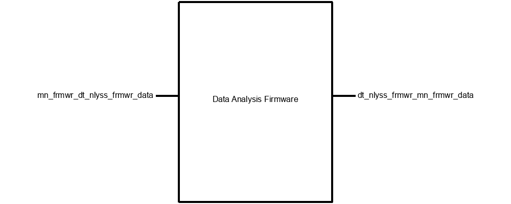
Block Description
This block entails analyzing swell data from the accelerometer including glider heading, significant wave height (meters), wave period (seconds), wave direction, maximum wave height, second highest wave height, maximum period, and spectral parameters for the Fourier Transform.
Interfaces
Main Firmware to Data Analysis Firmware
Signal Name: mn_frmwr_dt_nlyss_frmwr_data
Properties:
- Messages: Acceleration Data in N-Direction (32-bit floats): Acceleration North-South
- Messages: Acceleration Data in U-Direction (32-bit floats): Vertical acceleration data
- Messages: Acceleration Data in E-direction (32-bit floats): Acceleration East-West
Data Analysis Firmware to Main Firmware
Signal Name: dt_nlyss_frmwr_mn_frmwr_data
Properties:
- Messages: Dominant Period in E Direction (s)
- Messages: Dominant Period in U Direction (s)
- Messages: FFT Results in Upward (U) Direction (Real and Complex Values)
- Messages: FFT Results in Northward (N) Direction (Real and Complex Values)
- Messages: FFT Results in Eastward (E) Direction (Real and Complex Values)
- Messages: Dominant Period in N Direction (s)
SD Interface Firmware
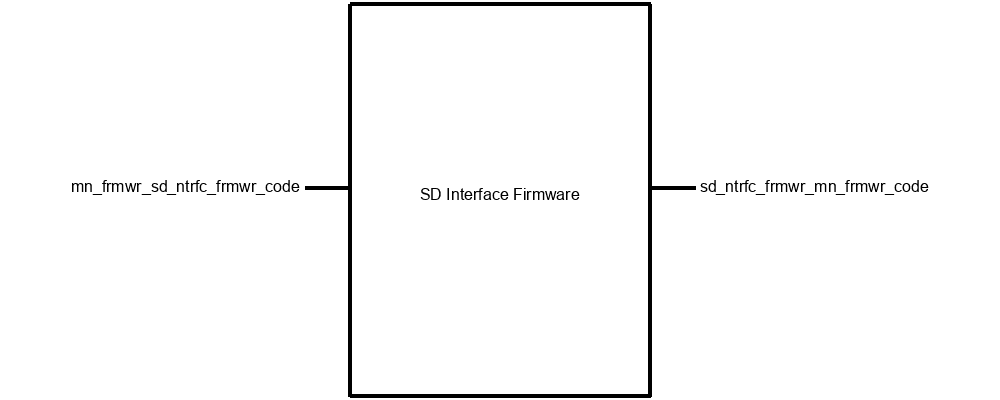
Block Description
This block will be a function library that will take an array of floats from the accelerometer board and converts it into data formatted to be saved to a file on the microSD card. The library will also have functions to perform the reverse of that operation- open a file on the microSD card and return an array of floats.
Interfaces
Main Firmware to SD Interface to MicroSD Firmware Code
Signal Name: mn_frmwr_sd_ntrfc_frmwr_code
Properties:
- Data: Populated array of floats
- Data: Populated Int Pointer
- Data: Null Int Pointer
- Data: Timestamp (Filename)
- Data: Null float array pointer
SD Interface Firmware Main Firmware Code
Signal Name: sd_ntrfc_frmwr_mn_frmwr_code
Properties:
- Return Value: Error Code
- Data: Populated array of floats from file on uSD
- Return Value: Number of floats Read
Function Definitions
#include#include #include #include "main.h" #include "fatfs.h" /* int formatSD(){ * * desc: formats the SD card to FAT file system * * inputs: none * * returns: int * 0 : returns 0 if successful * -1 : returns -1 if file system cannot be made * -2 : returns -2 if SD card cannot be mounted * -3 : returns -3 if SD card cannot be unmounted * */ /* int initFileSD(int fileName){ * * desc: takes an int as a filename, and creates a csv file called [int].csv. * It also adds header data. * * inputs: int fileName : name of file to write, '.csv' will be appended to it * * returns: int * -1 : returns -1 if SD card cannot be mounted * -2 : returns -2 if the file to be written cannot be opened/created * -3 : returns -3 if a write operation fails * -4 : returns -4 if the file close operation fails * -5 : returns -5 if the SD card unmount fails * else: returns number of bytes written to the SD card * */ */ int writeColSD(int fileName, float data[], int noElements){ * * desc: takes one array of floats, writes it to a file in the SD card. * * inputs: int fileName : name of file to write, '.csv' will be appended to it * float* data : an array containing the floats to be written to file * int noElements : an int representing the number of elements to write * * returns: int * -1 : returns -1 if SD card cannot be mounted * -2 : returns -2 if the file to be written cannot be opened/created * -3 : returns -3 if a write operation fails * -4 : returns -4 if the file close operation fails * -5 : returns -5 if the SD card unmount fails * else: returns number of bytes written to the SD card * */ */ int writeSD(int fileName, float data0[], float data1[], float data2[], float data3[], float data4[], * float data5[], float data6[], float data7[], float data8[], float data9[], float data10[], int noElements){ * * desc: takes eleven array of floats, writes them to a csv file in the SD card. * * inputs: int fileName : name of file to write, '.csv' will be appended to it * float* data0 - data10 : arrays containing the floats to be written to file. Should all be same length * int noElements : an int representing the number of elements from each array to write * * returns: int * -1 : returns -1 if SD card cannot be mounted * -2 : returns -2 if the file to be written cannot be opened/created * -3 : returns -3 if a write operation fails * -4 : returns -4 if the file close operation fails * -5 : returns -5 if the SD card unmount fails * else: returns number of bytes written to the SD card * */ */int readNoRowsSD(int fileName){ * * desc: takes a filename, and returns the number of rows in the file. The number of rows should be written * in the first line of the file. * * inputs: int fileName : name of file to write, '.csv' will be appended to it * * returns: int * -1 : returns -1 if SD card cannot be mounted * -2 : returns -2 if the file to be written cannot be opened/created * -3 : returns -4 if the file close operation fails * -4 : returns -5 if the SD card unmount fails * else: returns number of rows in file as read from first line of the file * */ /*int readSD(int fileName, float data[], int noElements, int column){ * * desc: takes a csv file on the SD cart and reads one column of the file into an array of floats. * * inputs: int fileName : name of file to write, '.csv' will be appended to it * float* data : an array containing the floats to be written to file * int noElements : an int representing the number of elements to write * int column : the column from from left to be read. Leftmost column is 0 * * returns: int * -1 : returns -1 if SD card cannot be mounted * -2 : returns -2 if the file to be written cannot be opened/created * -3 : returns -3 if a read operation fails * -4 : returns -4 if the file close operation fails * -5 : returns -5 if the SD card unmount fails * else: returns number of bytes written to the SD card * */ /*int readThreeColSD(int fileName, float data1[], int column1, float data2[], int column2, float data3[], int column3, int noElements){ * * desc: takes a csv file on the SD cart and reads three columns of the file into three arrays of floats. * * inputs: int fileName : name of file to write, '.csv' will be appended to it * float* data : an array containing the floats to be written to file * int noElements : an int representing the number of elements to write * int column1 : column 1 from from left to be read. Leftmost column is 0 * int column2 : column 2 from from left to be read. Leftmost column is 0 * int column3 : column 3 from from left to be read. Leftmost column is 0 * returns: int * -1 : returns -1 if SD card cannot be mounted * -2 : returns -2 if the file to be written cannot be opened/created * -3 : returns -3 if a read operation fails * -4 : returns -4 if the file close operation fails * -5 : returns -5 if the SD card unmount fails * else: returns number of bytes written to the SD card * */
Serial Interface Firmware
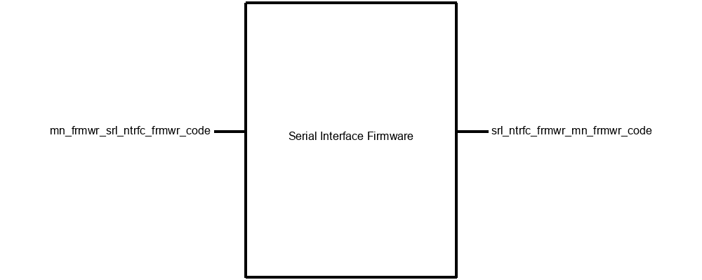
Block Description
This block configures, and uses the hardware on the STM32 microcontroller for serial communication with the ocean glider, and serial communication with the PC application. This block is a firmware library that the main firmware block will be able to call in order to send and receive data from either the ocean glider or the PC application. The main firmware will tell this block how to (and which) UART modules to configure. The main firmware will be able to pass this library data, as well as information on how to format that data, and which UART should transmit, and this library will configure the data correctly, and transmit it. Conversely, the main code will be able to request data from either of the UART modules, and the module should return the data in the order it is received, as well as the status of the UART modules, and whether data has been received but not passed to the main firmware yet.
Interfaces
Main Firmware Serial Interface Firware Code
Signal Name: mn_frmwr_srl_ntrfc_frmwr_code
Properties:
- Data: Numbers and strings to be transmitted via a UART Module
- UART Selection: Which UART interface should be used to transmit/receive
- Baud Rate: Speed the UART should operate at.
Serial Interface Firmware Main Firmware Code
Signal Name: srl_ntrfc_frmwr_mn_frmwr_code
Properties:
- Data Identifier: The type of data that is being received
- Status: Errors, and/or whether there is data in the receive buffers of the UARTs
- Data: Numbers and strings received from UART modules
Function Definitions
#include#include enum format { ACC_xyz, ACC_quat, ACC_mag, ACC_all, timestamp, UTC_time, restart }; enum status { data_available_1, data_available_2, data_available_both, data_available_none, error, no_error }; /* void UART_Init(void); * * desc: Initialize Ring Buffer * * inputs: none * * returns: void * */ /* int check_status(UART_HandleTypeDef *uart1, UART_HandleTypeDef *uart2); * * desc: check the status of the uart modules * * inputs: UART_HandleTypeDef *uart1: pointer to UART 1 handler * UART_HandleTypeDef *uart2: pointer to UART 2 handler * * returns: int * data_available_both: data is available in both UARTS * data_available_1: data is available in UART 1 * data_available_2: data is available in UART 2 * data_available_none: data is not available in either UARTS * */ /* void flush_buf(char* buf, unsigned int length) * * desc: flush a char buffer and fill with null character * * inputs: char* buf : character array to flush * unsigned int length : length of character array * * returns: void * */ /* void tx_string(UART_HandleTypeDef *uart, char* tx_buf) * * desc: generic send string * * inputs: UART_HandleTypeDef *uart : pointer to UART handler * char* tx_buf : buffer to transmit * * returns: void * */ /* void rx_string(UART_HandleTypeDef *uart, char* rx_buf, enum status* s) * * desc: generic receive string * * inputs: UART_HandleTypeDef *uart : pointer to UART handler * char* rx_buf : buffer for the received data * enum status* s : pointer to status, will be changed by function * * returns: void * */ /* void tx_accelerometer_data(UART_HandleTypeDef *uart, float* data, enum format f) * * desc: transmit accelerometer data in a specified format * * inputs: UART_HandleTypeDef *uart : pointer to UART handler * float* data : array of floats to transmit * enum format f : format of data to transmit * * returns: void * */ /* void rx_accelerometer_data(UART_HandleTypeDef *uart, float* data, enum format* f, enum status* s) * * desc: receive accelerometer data in a specified format * * inputs: UART_HandleTypeDef *uart : pointer to UART Handler * float* data : pointer to array of floats * enum format* f : pointer to format of the data received, changed by function * enum status* s : pointer to status of the operation, changed by funtion * * returns: void * */ /* void rx_set_time(UART_HandleTypeDef *uart, float* data, enum format* f, enum status* s) * * desc: receives UTC sent from the glider * * inputs: UART_HandleTypeDef *uart : pointer to UART handler * float* data : pointer where time from glider will be stored * enum format* f : pointer to format of the data received, changed by function * enum status* s : pointer to status of the operation, changed by funtion * * returns: void * */ /* void rx_restart(UART_HandleTypeDef *uart, enum format* f, enum status* s) * * desc: Looks for restart command from the glider * * inputs: UART_HandleTypeDef *uart : pointer to UART handler * enum format* f : pointer to format of the data received, changed by function * enum status* s : pointer to status of the operation, changed by funtion * * returns: void * */ /* int valid_float_characters(const char* data) * * desc: check a char aray and return true if it only contains characters from floating point nums and commas * * inputs: const char* data : array of chars to be checked * * returns: int * 0: Invalid charactars present * 1: All characters valid * */
PC Application
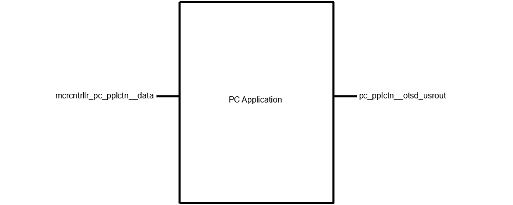
Block Description
This program is a python program that takes formatted data over UART and converts it to a .csv file.
Interfaces
PC Application Outside Userout
Signal Name: pc_pplctn__otsd_usrout
- Type: Text display of system status
- Type: 3D visualization of accelerometer orientation
- Usability: Any of the team members must be able to connect the system to a PC, open the application, and determine the system status.
- Datarate 115200 Baud
- Messages: Roll, Pitch Yaw, orientation in quaternions
- Cartesian (XYZ) Accelleration
- Protocol: UART
- PC Python Application
Microcontroller PC Application Communications
Signal Name: mcrcntrllr_pc_pplctn_data
Properties:
Downloads
Data Collection and Analysis
Project Partner Requirement
Engineering Requirement
- 1) Hs, Significant wave height in meters
- 2) Dom_period, dominant wave period in seconds
- 3) wave_dir, wave direction, magnetic
- 4) Hmax, maximum wave height in meters
- 5) Hmax2, second highest wave height
- 6) Pmax, maximum period
- 7) ([AB]|[12]) directional wave spectra parameter
- 8) Wave component number
Testing Process
- Power system and hook up to PC Application built for testing.
- Run the system for 20 minutes.
- Save the parameters calculated by the system
- Ensure that there are at least 12,000 data samples measured and the last time stamp ensures that 20 minutes have elapsed.
- Remove SD card from system and connect to PC
- Use a script that has been approved by the project partners to manually calculate the parameters from the raw data that was collected.
- Compare the parameters calculated by the system, and the parameters calculated by the script. This requirement will be met if the two calculations differ by no more than 5% for each parameter.
Verification Evidence
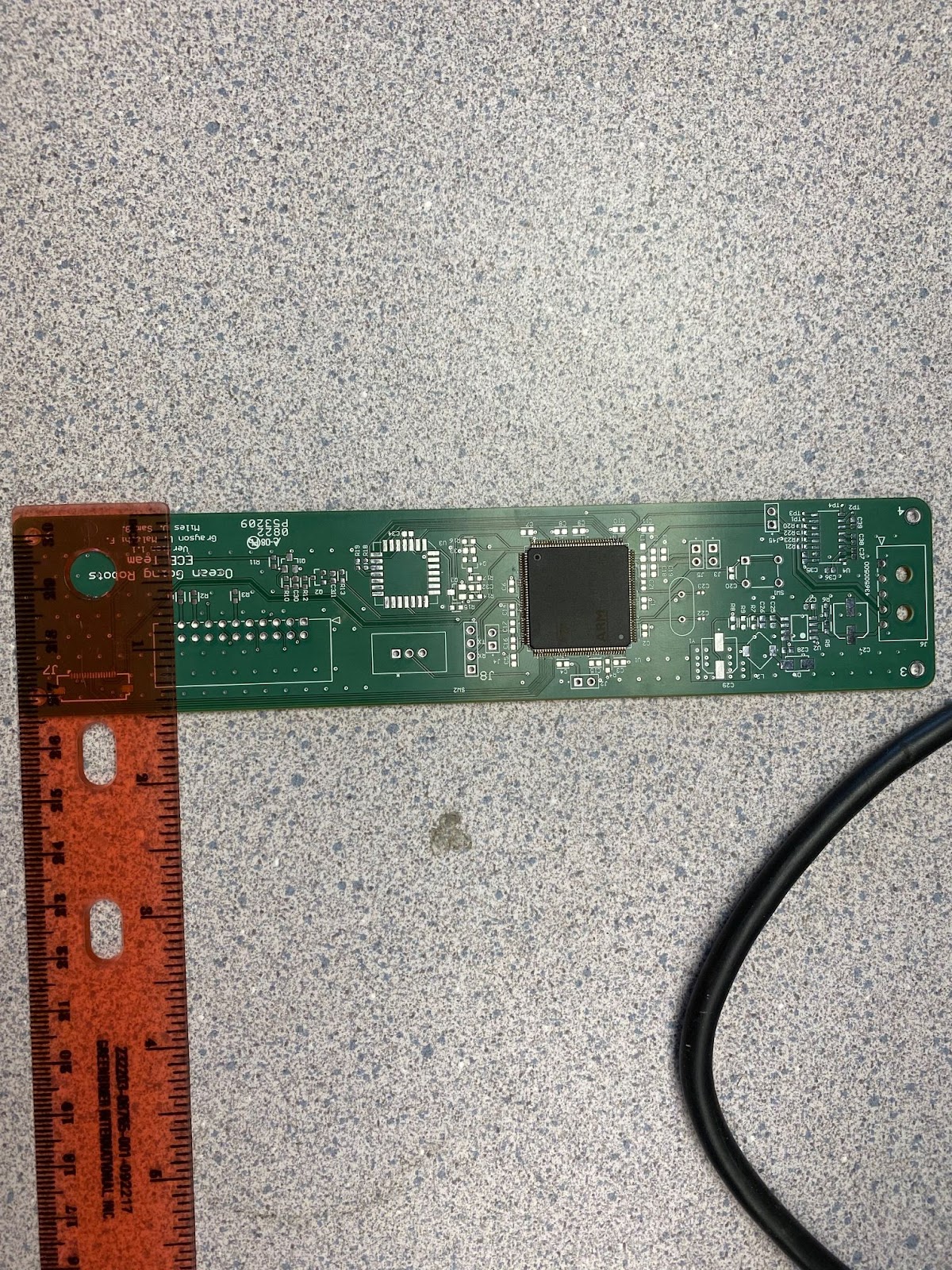
PCB Size
Project Partner Requirement
Engineering Requirement
Testing Process
- Measure length of PCB.
- Measure width of PCB.
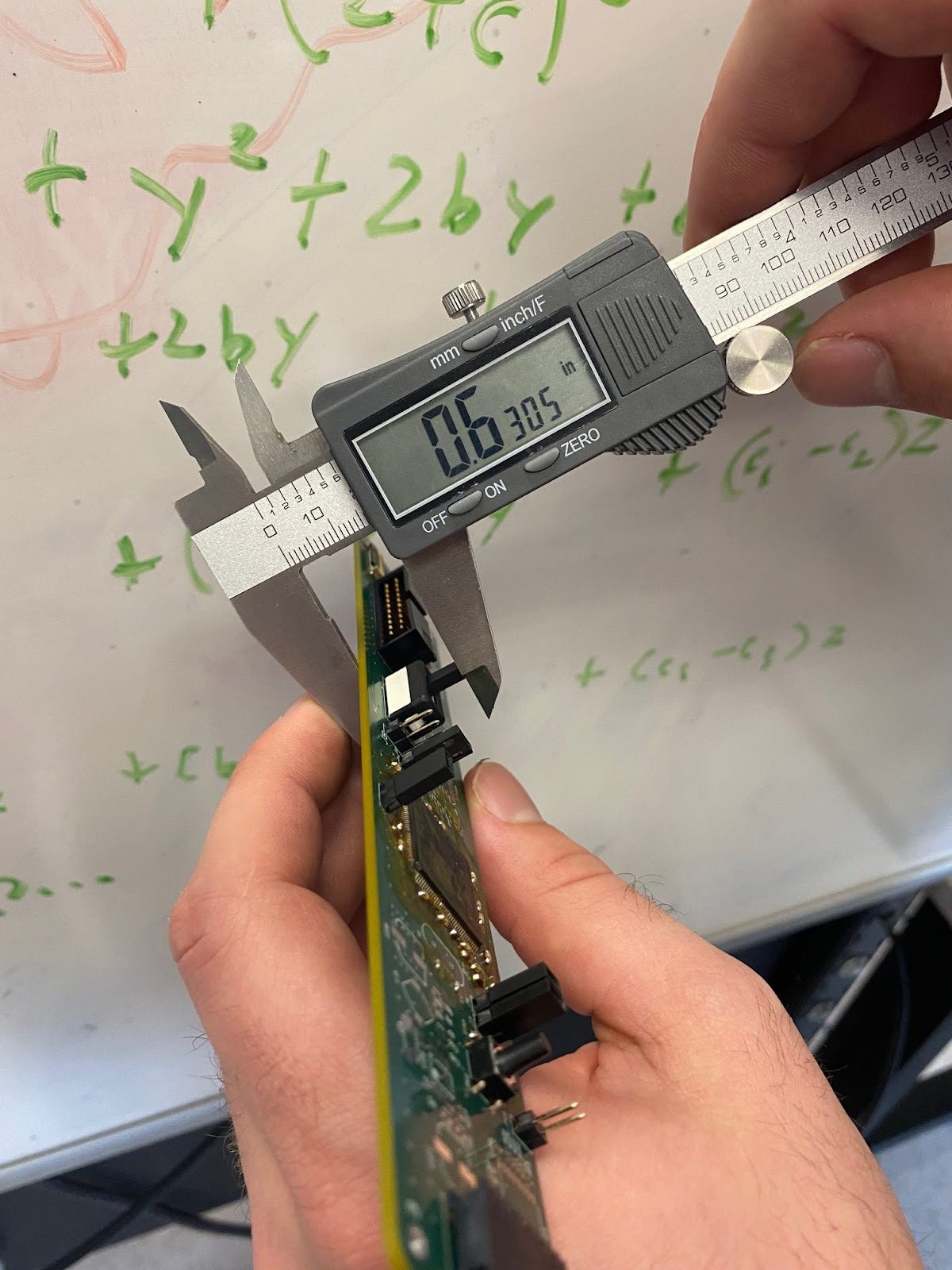
- Measure height of PCB.
- Ensure that measurements are smaller than requirements (7 inches long, 1.5 inches wide, and 2 inches tall).
Verification Evidence
In the following images, we see that the pcb size is adequate according to our engineering requiremtnes.
Removable Data Storage
Project Partner Requirement
Engineering Requirement
Testing Process
- Collect data for 5 minutes
- Remove memory card
- Check if the memory card has at least 3,000 samples.
Verification Evidence
The video link below shows the system being powered up, the initialization commands being passed to the system using serial communication, the data being collected, and verification that over 3,000 data samples have been taken.
Glider Battery Life
Project Partner Requirement
Engineering Requiremens
Testing Process
- Run a full 20 minute data collection cycle.
- Measure the voltage on either side of a current-sensing resistor at the system’s input for 20 minutes using an oscilloscope and export the waveforms as a .csv file for post-processing.
- Using MATLAB, calculate the instantaneous current and power over the entire 20 minute collection window.
- Integrate the instantaneous power with respect to time to find the cumulative energy in Joules.
- Compare the final calculated value for energy with the maximum energy value of 230 Joules.
Verification Evidence
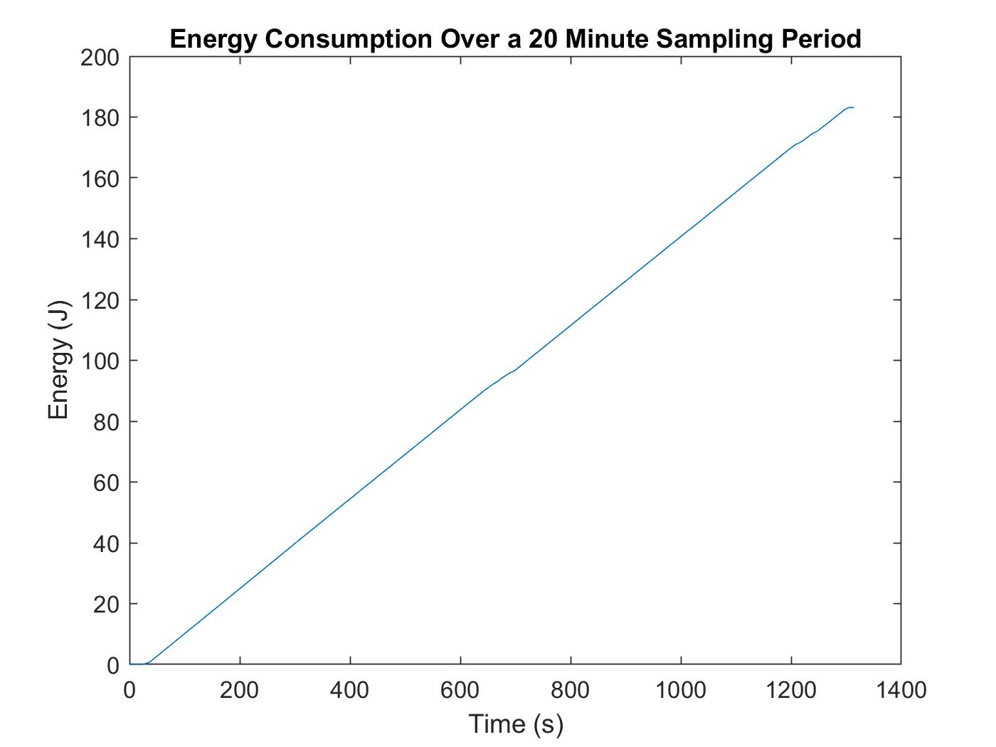
After running the devised MATLAB script to achieve the functionality listed above, two plots were created including a plot of Instantaneous Power and Cumulative Energy as shown in Figures 5.5.1 and 5.5.2 below. As shown in Figure 5.5.2, the total energy consumption at the end of the 20 minute collection cycle was 183.111 J, significantly less than the maximum energy consumption listed above of 230 Joules.
.Plot of instantaneous power consumption over a 20 minute data collection cycle generated using MATLAB.

Plot of cumulative energy consumption over the 20 minute data collection cycle generated using MATLAB. Note the maximum energy consumption peaks at a value of 183 J (below our target of 230 J).
Data Ease of Access
Project Partner Requirement
Engineering Requirement
Testing Process
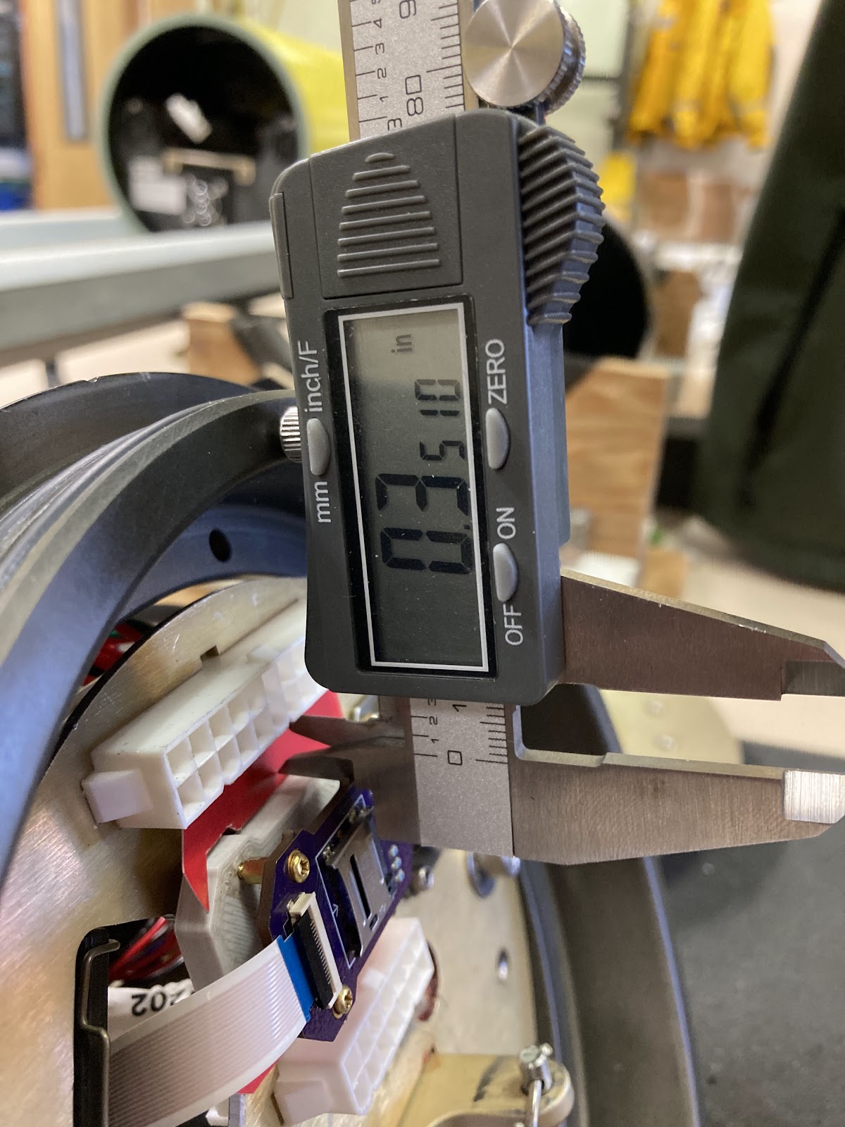
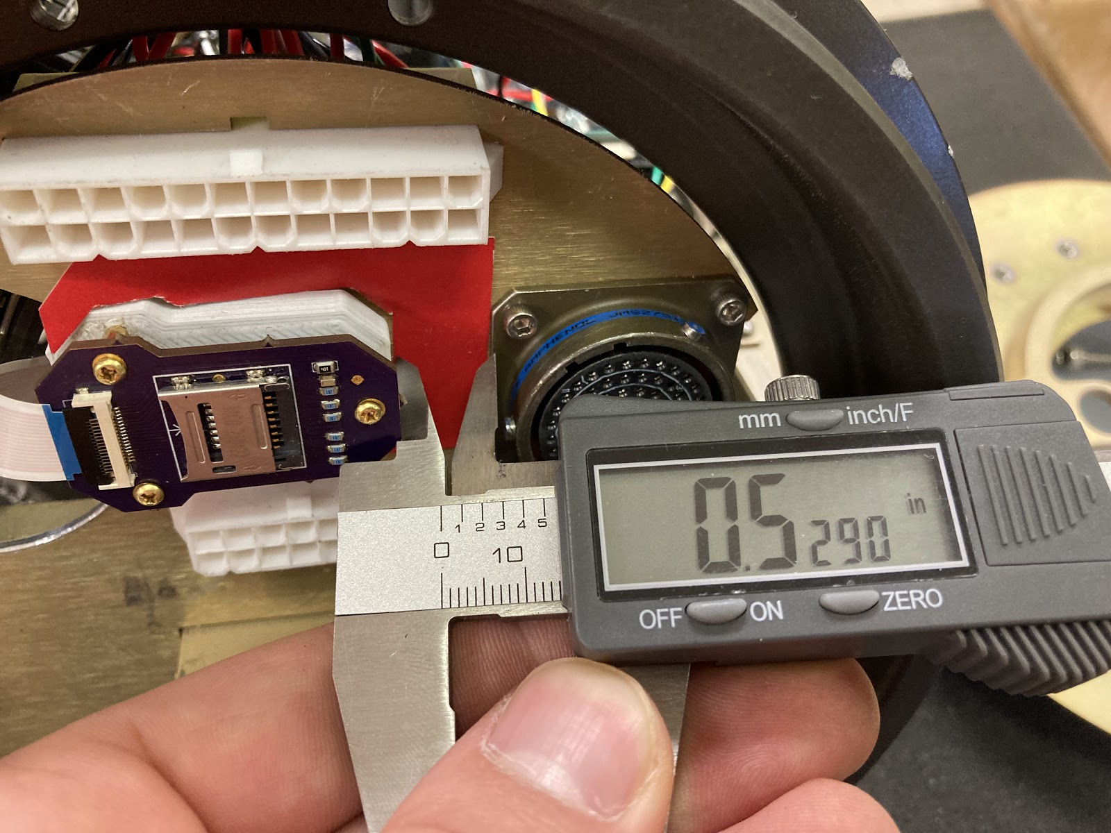
- Install SD card and associated PCB into the glider see Figure 2.1.
- Measure the distance to the connectors.
- This will be successful if the measurements are less than or equal to 0.5 inches from the connector with the screw on collar and 0.25 inches from the white plastic connectors.
Verification Evidence
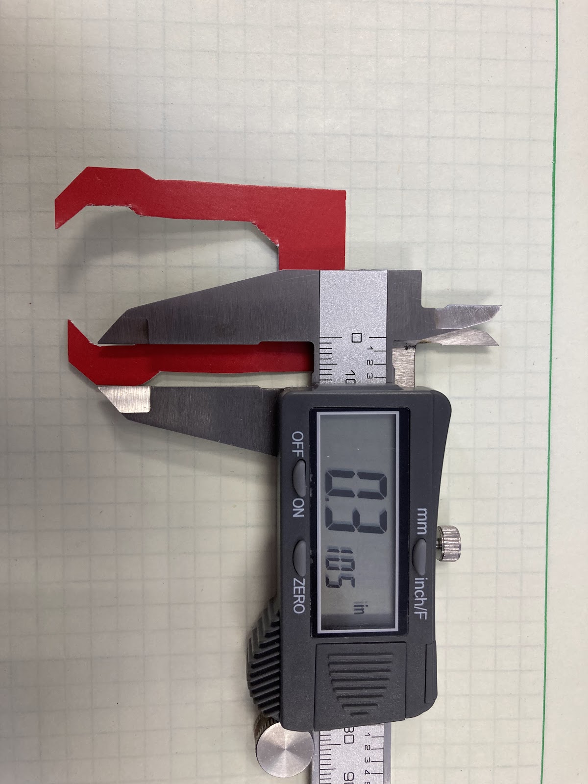
The SD board was affixed to a 3D printed bracket which was installed into the glider with double sided tape to measure the connector clearances as was suggested by our project partners. In addition to directly measuring the clearances with a set of calipers, we also created a template out of cardstock the width of our minimum clearance dimensions that fits around the bracket. By showing that the template fits between the connectors with the bracket and SD board mounted, our clearances can be easily verified visually.
In the following images, we see that the clearances are adequate according to our engineering requiremtnes.
In the following images, we see the cardstock also demonstrating correct clearances.


Wiki Page
Project Partner Requirement
Engineering Requirement
Testing Process
- Write the initial draft of the Wiki Page and submit to the Project Partners by the Friday of Week 9 Winter 2022
- Receive feedback from the Project Partners by the Friday of Week 10 Winter 2022
- Write the final draft of the Wiki Page and submit to the Project Partners by the Friday of Week 3 Spring 2022
- If Pat Welch (Project partner) finds the Wiki sufficient, he will give his approval before system verification (Week 6 Spring 2022).
Verification Evidence
The Project Wiki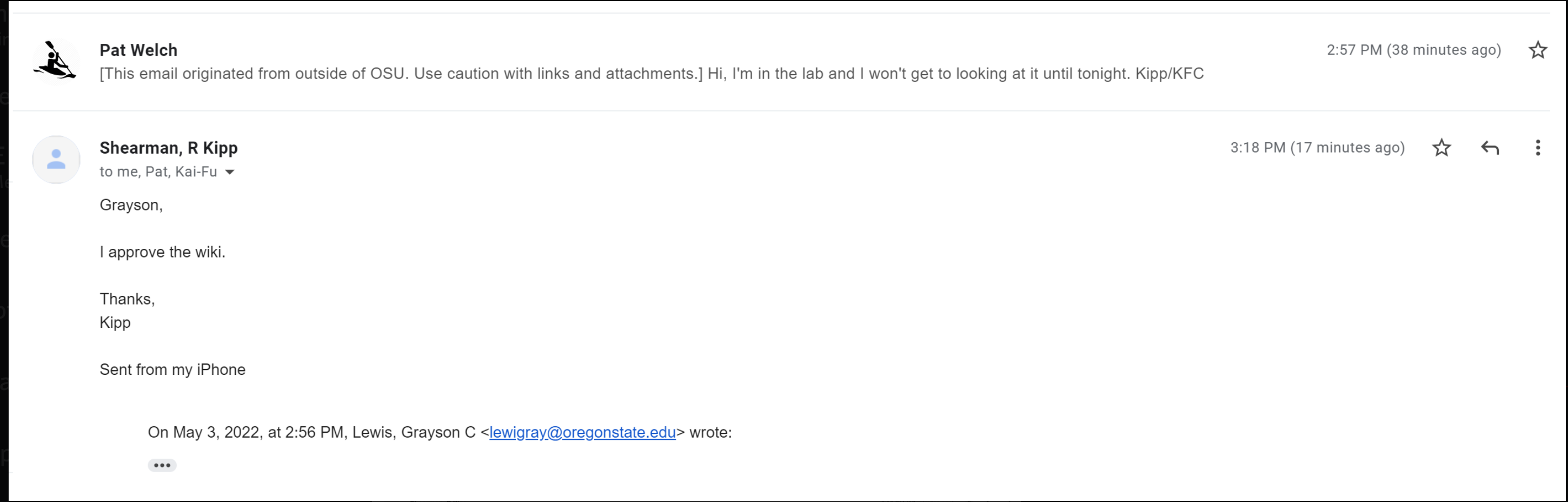
System Longevity
Project Partner Requirement
Engineering Requirement
Testing Process
- During a 90 day period, the system will be cycled 1080 times, a cycle consisting of the system being powered on, collecting data for 20 minutes, processing/storing the collected data, and then being powered off. To demonstrate the system will not encounter any errors in this 90 day period, we will cycle it 206 times, with a reduced data collection time.
- For 100 cycles, capture 10 seconds of data and then reset the system, cycle the power, and do it again.
- The system shall not encounter any hardware malfunctions or firmware errors and acceleration data shall be stored on the SD card.
Verification Evidence
System Security
Project Partner Requirement
Engineering Requirement
Testing Process
Enclose the system in the test enclosure.
Drop enclosure from 10 ft above the surface of a water tank (specific tank TBD).
Remove system from test enclosure.
Connect system to power source.
Ensure serial communication (including the transmission of the 13 final parameters) is still functioning.