The navigation systems used in the cockpit include:
1) Navigation Maps or Sectionals
Navigation Maps or Sectionals both visual flight rule (VFR sectionals) and instrument flight rules (IFR sectionals)
3) Guidance Surveillance and Control
5) Global Positioning Systems and many others
6) On board navigation computers
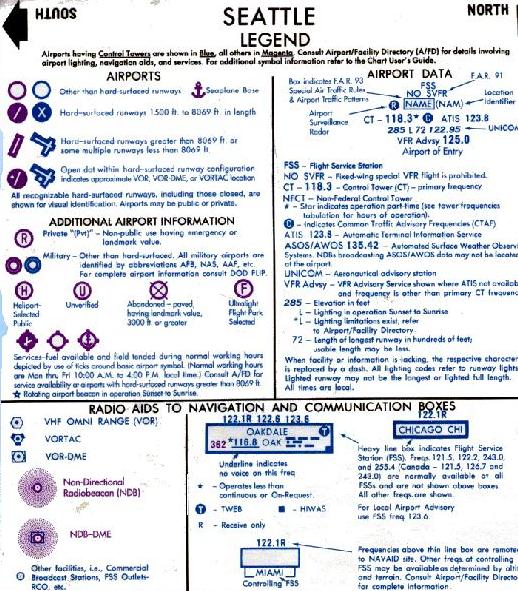
Example VFR Sectional Information for Seattle Region (Reference: 5)
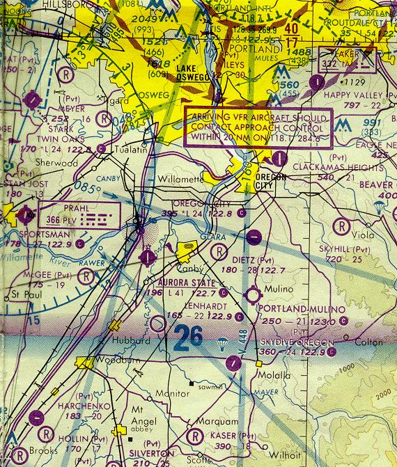
Sample of Visual Flight Rule (VFR) Flight Sectional (Reference: 5)
Information for an airport located in Class C Airspace
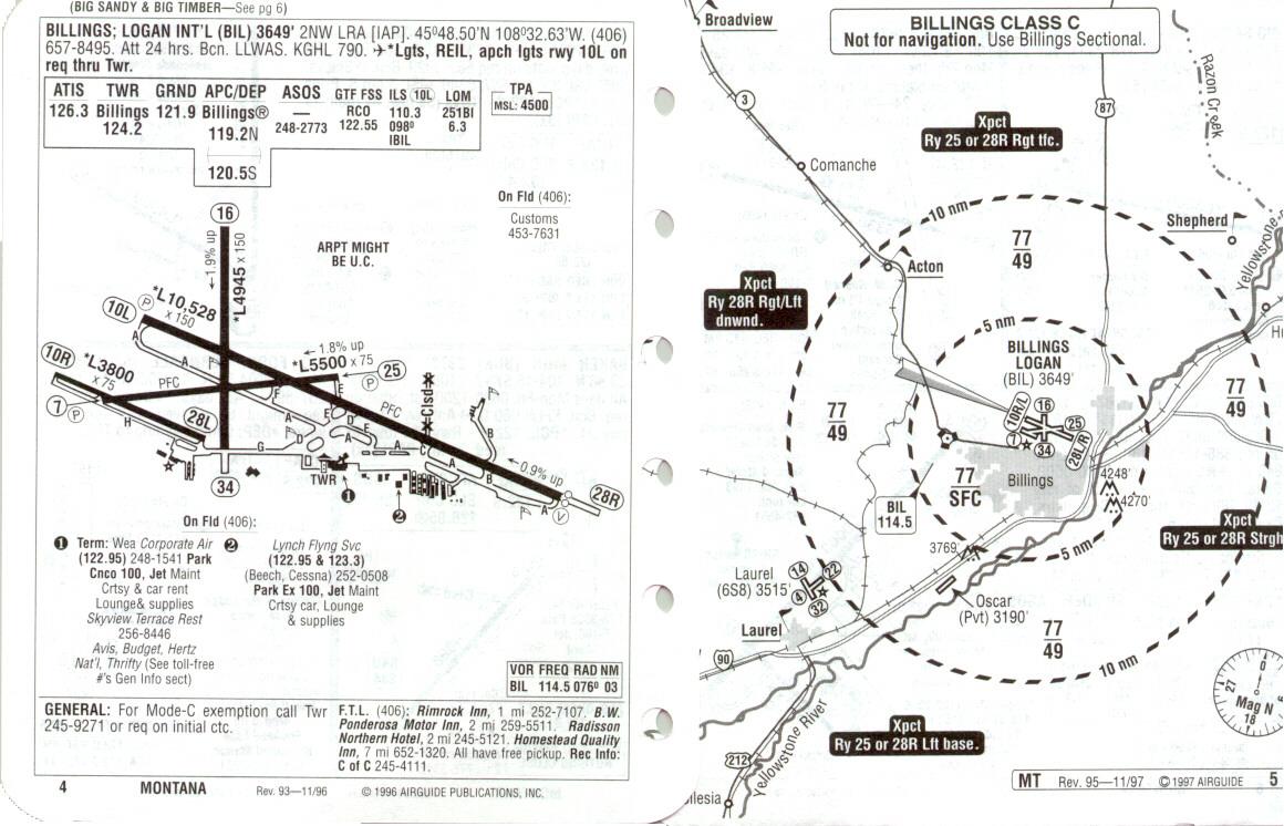
Airport Information (Reference 4)
Terminology
IMC- instrument meteorological conditions: low visibility conditions
IFR -Instrument Flight Rules govern flight
VMC- visual meteorological conditions:
VFR -Visual Flight Rules:
Basic VFR minima are:
3 nautical miles visibility
500 feet below the clouds
1000 feet above the clouds
2000 horizontally from clouds
Above 10,000 feet mean sea level (MSL) the VFR minima are:
5 miles visibility
1000 feet below or above the clouds
1 mile horizontally from the clouds
An ILS or similar system is used in instrument meteorological conditions- IMC.
Two radio beams define the glide slope to runway, one is the glide slope indicator and the other is the localizer that indicates to pilots their horizontal deviation from the runway centerline. The typical glide slope ranges between 3o to 7.5o . Other indicators are also provided to indicate how far the aircraft is from the end of runway. These are called the inner and outer marker. Aircraft are spaced according to size of aircraft and approach speeds, as well as according to VFR or IFR operations. See figure below for a sketch of an ILS system.

Reference: 3, page 109
Global Positioning System (GPS) A new landing system using differential GPS is being developed, however most systems are still waiting for final approval from the FAA. The GPS systems show great promise for small airports that can not afford ILS systems.
Microwave Landing System (MLS) is a sophisticated landing systems that was originally developed to overcome problems of the ILS system. Development of this landing systems was overtaken by the more rapid adoption of the new GPS based landing systems.
Almost all commercial and corporate aircraft have on board navigation computers, and most airlines have “company” data links with their aircraft. The data links help to reduce the amount of voice and radio communication between the aircraft and ground operations. Many general aviation pilots use lap top computers and hand held navigation equipment as well.
The national airspace system consists of a network of navigational aids and a number of air traffic control facilities.
Air Traffic control is used:
i) to prevent collisions between aircraft
ii) to control the maneuvering area between aircraft on the ground and obstructions such as mountains
iii) to expedite and maintain an orderly flow of air traffic
There are three parts in the air traffic control process:
i) en route
ii) terminal
iii) oceanic.
Terminal Air traffic control is divided into the radar approach control TRACON, and air traffic control tower ATCT.
Air Traffic Control Radar Beacon System –ATCRBS Monitors aircraft location for those equipped with transponders. Aircraft are equipped with altitude encoding transponders that indicate aircraft identity and altitude on radar scope. Many old and very small general aviation aircraft are not equipped with transponders. Aircraft that do not have transponders can not enter certain types of airspace such as class D or higher.
Automated Radar Terminal System- ARTS (I-III) I- basic, III sophisticated- supports air traffic control
Airport Surveillance Radar- ASR newest level also has weather information
Air Route Surveillance Radar- ARSR- tracks aircraft location and separation and has information on the identification of the aircraft, destination, flight plan, estimated speed and flight altitude.
Air Route Traffic Control Center- ARTCC: controls the movement of en route aircraft along the airways and jet routes and in other parts of the airspace. Each of the 20 ARTCC in the country has control over a geographic area that may be as large as 100,000 mi2. At the boundary of the sector, control is transferred to an adjacent radar service center.
Airport Traffic Control Tower- ATCT -is the facility that supervises, monitors and directs the arrival and departure aircraft at the airport and in the immediate airspace within about 5 miles from the airport. The ATCT is responsible for issuing clearances for departing aircraft as well as providing information on local weather conditions. In the USA, about 400 air traffic control towers are operated by the FAA, but there are others that are operated under contract to the FAA.
Automated Terminal Information Service- ATIS – provides airport information for pilots approaching and airport. In general, the pilot calls into ATIS to get information before they call into the tower. ATIS cuts down on the amount of voice communication between the tower and the pilots and provides information that all the approaching aircraft require. Information includes current weather and barometric pressure, active runways and any other information that the pilots might need.
Terminal Radar Approach Control -TRACON- usually controls from 5 miles to 50 miles from the airport and up to an altitude of 17,000 feet, and the area is referred to as the terminal area. The approaching aircraft are received from the ARTCC. The TRACON may control several airports in the region. For example, Portland controls Hillsboro and Troutdale.
Central Flow Control Function- CFCF- (Aircraft scheduling) now referred to as the Air Traffic System Command Center- ATSCC
En-route Flight Advisory Service- EFAS -; issues weather and other alerts en route
Precision Approach Radar- PAR – is a hold over from the military and World War II
Wind Shear (sudden change in wind velocity and direction). Wind shear is usually a result of microburst from thunderstorms. Doppler radar is a tool that is used to monitor and predict wind shear
Wake vortex or wake turbulence is due to vortices that form at the ends of the wings when the wings provide lift. These vortices are made up of two counter rotating cylindrical air masses about a wingspan apart. The velocity of the wind within these cylinders can be hazardous to other aircraft encountering them in flight. The speed for the vortices are directly proportional to the weight of the aircraft and inversely proportional to the speed The more intense vortices are generated when the aircraft is flying slowly near an airport.[1]
As a result of research of wake turbulence, the FAA has divided airline jet aircraft into two classes: heavy and large. The heavy includes wide bodied jets and aircraft with a maximum takeoff weight of over 300,000 pounds. In addition this has resulted in revisions in aircraft spacing for air traffic control.
Table horizontal Separation in Landing for Arrival-Arrival Spacing of Aircraft on Same Runway Approaches in VFR and IFR conditions, nmi
VFR* |
IFR ( wake vortex) |
|||||
Trailing Aircraft Type |
Trailing Aircraft Type |
|||||
| Leading Aircraft Type | Heavy |
Large |
Small |
Heavy |
Large |
Small |
| Heavy Large Small |
2.7 1.9 1.9 |
3.6 1.9 1.9 |
4.5 2.7 1.9 |
4.0 3.0 3.0 |
5.0 3.0 3.0 |
6.0 4.0 3.0 |
These values are shown to approximately represent these operation and are not regulatory in nature.
Source: Federal Aviation Administration, Parameters of Future ATC Systems Relating to Airport Capacity and Delay, Rep. FAA_EM-78-8A, Federal Aviation Administration, Washington, D.C. 1978
Table Separation from Same-Runway consecutive Departures VFR and IFR conditions, s
VFR* |
IFR ( wake vortex) |
|||||
Trailing Aircraft Type |
Trailing Aircraft Type |
|||||
| Leading Aircraft Type | Heavy |
Large |
Small |
Heavy |
Large |
Small |
| Heavy Large Small |
90 60 50 |
120 60 45 |
120 50 35 |
120 60 60 |
120 60 60 |
120 60 60 |
These values are shown to approximately represent these operation and are not regulatory in nature.
Source: Federal Aviation Administration, Parameters of Future ATC Systems Relating to Airport Capacity and Delay, Rep. FAA_EM-78-8A, Federal Aviation Administration, Washington, D.C. 1978
Automatic Weather Observation System (AWOS), these are enhanced automated weather observations that can be transmitted by datalink to pilots.
Aircraft noise has many dimensions, and most of these relate to the reaction of people to noise. As a result of this, the day-night average sound level DNL is a metric used to describe sound exposure over at 24 hour period, and is the most common metric for aircraft noise control. Noise abatement projects are used to mitigate or manage noise that may result from changes in airport activities. Changes in airport activities, or structure will almost always require changes in related land use activities. Noise control is a major activity at airports and many large airports have very sophisticated noise management programs and monitoring systems. In recent years, advances in jet engine technology has impacted sound levels. Most jets today are much quieter than their predecessors. The FAA has also modified landing and take off procedures to be sensitive to surrounding land use patterns.
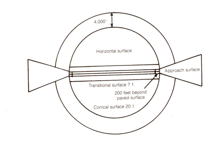
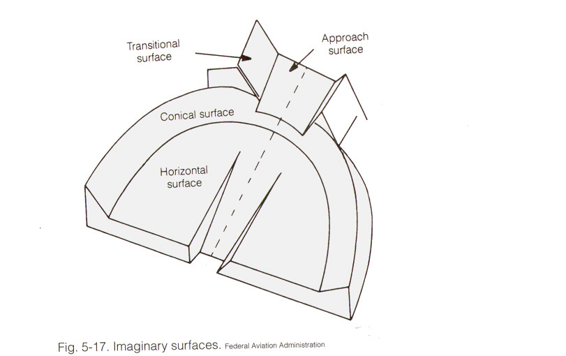
(Objects affecting Navigable Airspace) establishes standard for determining obstructions in navigable airspace, and sets forth the requirements for notice to the FAA due to certain proposed construction or alteration activities, and provides for aeronautical studies of obstructions to air navigation to determine the effect of these obstructions on the safe and efficient use of airspace. [1] It is important for airport operators to understand the implications of FAR Part 77, and their responsibility for insuring that the aerial approaches are protected. Often it is necessary to create zoning protection to limit the types of land use, and heights of objects in the airport vicinity. Subpart C of FAR Part 77 established standards for determining obstructions to air navigation. The standards apply to existing and manufactured objects, objects of natural growth, and terrain.
The FAR Part 77 can be accessed at: http://www.faa.gov/avr/AFS/FARS/far-77.txt
or
In PDF Format at FAR Part 77
Reference: 3, page 118
http://www.faa.gov/avr/AFS/FARS/far-77.txt
Reference: 3, page 118
Bozeman Montana
Airport Information